Seakeeper 4 Operation Manual (90761-1)
2.0 System Overview
2.1 System Overview Introduction
The Seakeeper 4 uses gyroscopic principles to dampen cyclic boat roll motions in waves and wakes. In installations involving multiple Seakeepers, each Seakeeper operates independently of one another; therefore, this manual only discusses the operation of a single unit.
Reduction of boat roll is a function of the boat’s displacement, transverse metacentric height (GMT), and hull damping as well as the operating conditions (speed and heading with respect to waves) and sea state. Seakeeper’s active control regulates the hydraulic brake to ensure the Seakeeper’s anti-roll torque is maximized irrespective of hull characteristics or operating conditions.
Operation of the Seakeeper 4 requires mechanical, electrical, and plumbing interfaces with the boat. Figure 1 illustrates the interconnection of these components and their interface with the boat. The Seakeeper 4 requires a connection to a display to support the Seakeeper Application; display options include a compatible MFD or Seakeeper 5” Touch Display.

Seakeeper 4 technical specifications provided in Section 7, list the power consumption, total weight, and dimensions of the major components. Gyroscopic principals that apply to boat roll control are discussed on
Seakeeper’s website at www.seakeeper.com. The Seakeeper website also contains videos of Seakeeper operation and a variety of different boats operating in waves with the Seakeeper on and off. It is recommended that the reader play these videos prior to reading the remainder of this manual.
2.1.1 PRECAUTIONS

There is a large torque about the gimbal axis when the Seakeeper is precessing. Seakeeper cover panels are provided to prevent personnel or equipment from contacting the Seakeeper while it is in operation.
__________________________________________________________________________________________________
The Seakeeper covers should not be stood on or have anything placed on top. The covers should always be in place during operation.
__________________________________________________________________________________________________
If it is ever necessary to touch the Seakeeper while the flywheel is spinning, the Seakeeper must be locked (taken out of SEA MODE) at the display to stop the Seakeeper from precessing.
__________________________________________________________________________________________________
Seakeeper maintenance should not be attempted unless the Seakeeper is locked, the flywheel has stopped spinning, and AC power has been disconnected for at least 10 minutes.
2.1.2 SAFE BOAT OPERATION

Boat operators are advised that the Seakeeper’s sole function is to dampen a boat’s cyclic roll motions. The
Seakeeper is not, and is not intended to be, a substitute for adequate hull stability about the pitch, roll and yaw axes and the Seakeeper is not designed to prevent any instability due to improper boat operation, including, without limitation, any aggressive maneuvers at high speed. During aggressive maneuvers at high speed, the Seakeeper outputs a constant pitch moment which can create a small bow-down or bow-up trim change.
Improper boat operation including, without limitation, aggressive maneuvers at high speed can result in the boat becoming unstable. If you intend to operate the boat in such a manner, you should lock the Seakeeper
in the vertical position before operating the boat in that manner. This is easily accomplished by turning the boat to starboard at slow speed in the Stabilize mode. After turning to starboard for 5 seconds, turn the Stabilize mode off while continuing to turn and then go to the Service Page on the display and confirm the Gyro Angle is within +10 degrees of 0 degrees.
2.2 Seakeeper Assembly
The Seakeeper assembly consists of a flywheel housed in a cast aluminum vacuum-tight enclosure. The flywheel spins about a vertical axis and is supported by upper and lower pairs of bearings. A DC brushless motor mounted inside the enclosure spins the flywheel at high speed.
The enclosure is fastened to two gimbal shafts that are supported by gimbal bearings on either side. These shafts establish an athwartship gimbal axis about which the flywheel and enclosure precess or rotate up to
+/- 60 degrees during operation. The gimbal bearings are supported by a foundation which is attached to the hull structure. This foundation transfers the loads that the Seakeeper produces to the hull structure.
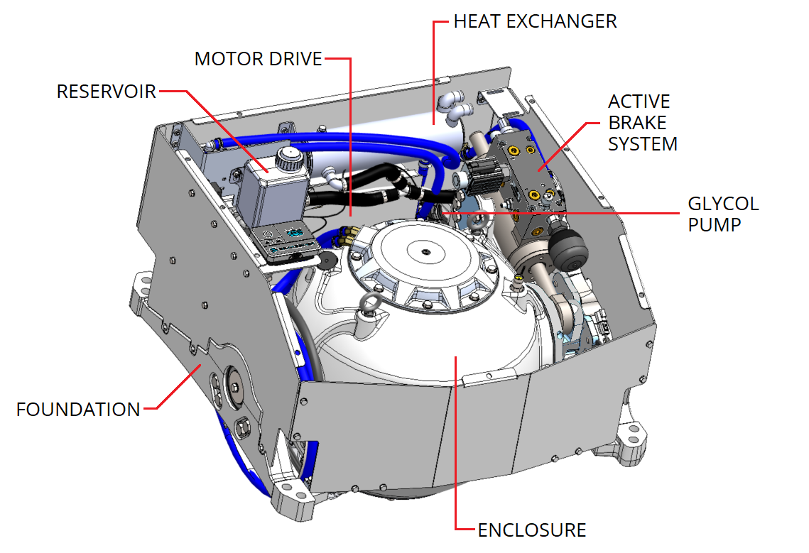
An active hydraulic brake mechanism is located on the Seakeeper assembly to regulate the Seakeeper’s precession motions about the gimbal shaft. It includes one hydraulic cylinder and an integrated hydraulic manifold.
A coolant pump, heat exchanger, and reservoir are located on the rear panel interior. A glycol/water mix is circulated through a closed loop to the drive box, hydraulic manifold, and the end caps of the enclosure to remove heat.