Seakeeper 4 Operation Manual (90761-1)
3.3 Operating Instructions
3.3.1 Start Up
The Seakeeper should be shut down when stabilization is no longer required. This maximizes the longevity of the Seakeeper.
- Energize Seakeeper 4 Battery Isolation Switch.
- Energize Seakeeper 4 High Current DC Power Supply (12 VDC, 100 A) at customer-supplied circuit breaker.
- Energize 12 VDC Seawater Pump power supply at the customer-supplied circuit breaker (N/A if fuse is supplied as overcurrent protection).
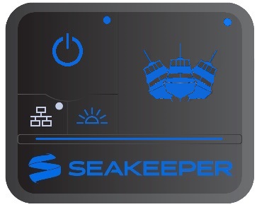
- When the high DC power is turned on, the ConnectBox and MFD application or Seakeeper 5” Touch Display will initialize as seen below. The Seakeeper 4 can be powered on and controlled by either the Seakeeper Application or the ConnectBox.
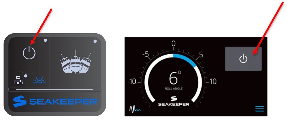
- With system energized, check the Seakeeper display for any ALARMS. If there are any ALARMS present. Alarms must be addressed to proceed.
- To turn the Seakeeper on, press the POWER button; the button will turn blue. The progress bar will appear and indicate how soon the Seakeeper will be available for stabilization. The progress bar indicates the speed of the flywheel as it accelerates to its rated operating RPM.
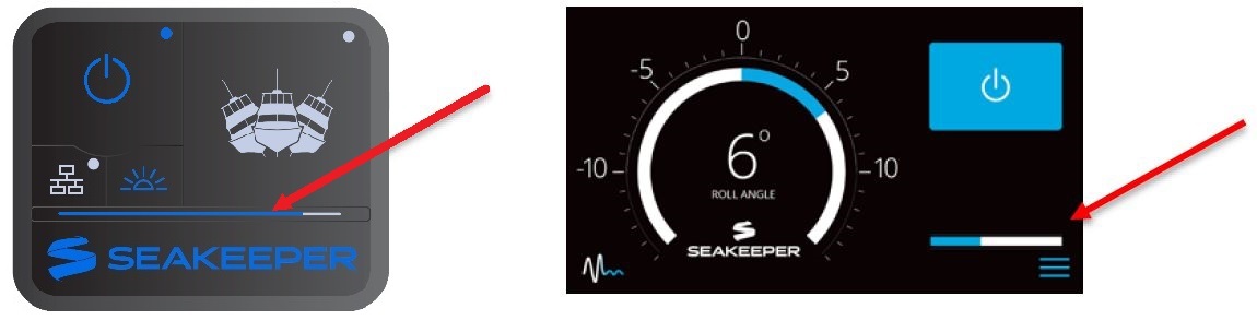
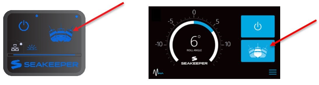
- When the Seakeeper is initialized and up to Stabilization RPM the STABILIZE button will appear on the application, or if using the ConnectBox, the STABILIZE button will illuminate blue and pulsate. At this point, the Seakeeper is available for stabilization by pressing the STABILIZE button.
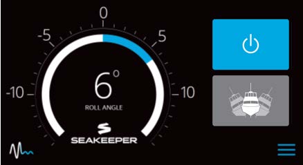

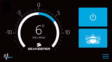
- The progress bar indicating flywheel spool-up will disappear from the display screen once the STABILIZE button is pressed (turns blue) and the ConnectBox will fully illuminate. At this point, the Seakeeper has reached its rated operating RPM and maximum stabilization is available. If the STABILZE button has not been pressed (button is grey), pressing the button will turn it blue and stabilization will be provided. The seawater pump will cycle on and off based on the operating temperature of the Seakeeper 4.
3.3.2 Stabilization

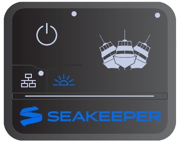
If it is necessary to shut off power to the flywheel motor and slow the flywheel for any reason, press Seakeeper On/Off button; the button will turn grey and the Stabilize button will disappear, indicating the command has been accepted. It takes approximately 8+ hours for the speed to slow to 0 RPM.
___________________________________________________________
If it is necessary to stop Seakeeper motion for any reason, press the Stabilize button. The Stabilize button will turn grey indicating that the Seakeeper is locked. Never attempt to work on the Seakeeper until the flywheel has stopped spinning. In the event that the brake system has automatically locked the Seakeeper due to an alarm or failure, no attempt should be made to bypass the alarm or automatic lock.
To stabilize the vessel after the Seakeeper is On and the flywheel is above the minimum stabilization RPM, press the STABILIZE button. The button will turn blue indicating that the Seakeeper is stabilizing the roll motion.
Boat operators are advised that the Seakeeper’s sole function is to dampen a boat’s cyclic roll motions. The Seakeeper is not, and is not intended to be, a substitute for adequate hull stability about the pitch, roll and yaw axes and the Seakeeper is not designed to prevent any instability due to improper boat operation, including, without limitation, any aggressive maneuvers at high speed. During aggressive maneuvers at high speed, the Seakeeper outputs a constant pitch moment which can create a small bow-down or bow-up trim change.
Improper boat operation including, without limitation, aggressive maneuvers at high speed can result in the boat becoming unstable. If you intend to operate the boat in such a manner, you should lock the Seakeeper in the vertical position before operating the boat in that manner. This is easily accomplished by turning the boat to starboard at slow speed in the Stabilize mode. After turning to starboard for 5 seconds, turn the Stabilize mode off while continuing to turn and then go to the Service Page on the display and confirm the Gyro Angle is within +/-10 degrees of 0 degrees gimbal angle.
3.3.3 Normal Shutdown
The Seakeeper should be stopped when stabilization is no longer required. Once the vessel is secured in the slip, the high and low current DC power to the Seakeeper should be switched to the Off position. The Seakeeper will continue to spool down to 0 RPM. No cooling is required during this time. Note Seakeeper will take 8+ hours to coast down to 0 RPM from full speed.
Note: The seawater pump may run for up to 5 minutes after the Seakeeper is switched off and is coasting (with low current DC power applied).
The Seakeeper should be shut down when stabilization is no longer required. This maximizes the longevity of the Seakeeper.
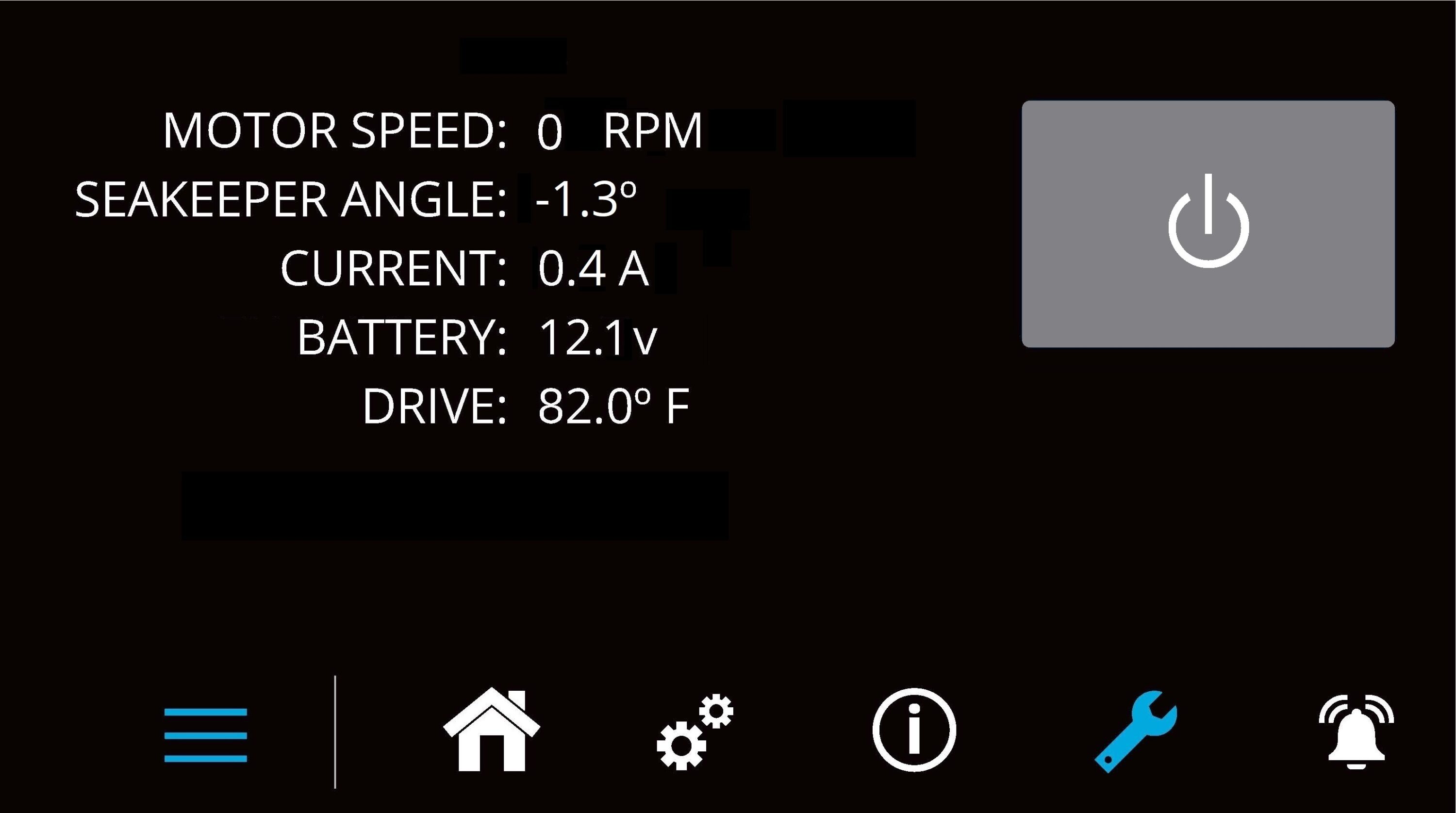
- Press the Seakeeper POWER button. The POWER button will turn grey. The Seakeeper will discontinue stabilization and the flywheel will start coasting.
- Once the vessel is secured in the slip, switch the high current and low current DC power to the Seakeeper off. The flywheel will continue to spool down to 0 RPM. This can take 8+ hours from full speed. When the flywheel has stopped spinning, 0 RPM will appear on the service screen.
4.0 Power Failures, Alarms, and Troubleshooting
4.1 Power Failures, Alarms, and Troubleshooting Introduction
The Seakeeper 4 has safety features, such as alarms and warnings, that pop-up on the Seakeeper
Application and are signaled on the ConnectBox to protect the Seakeeper as well as the vessel. The brake can be locked from the Application, ConnectBox or by shutting off DC power at the supply breakers, preventing the Seakeeper from precessing.
4.2 Power Failures
The Motor Connections should not be touched when the Seakeeper is Powered on, or the motor is running. This voltage hazard exists even if the flywheel is coasting down, and the supply voltage has been shut off.
________________________________________________________________________________________________
The flywheel must be at Zero (0) RPM and DC input power disconnected for at least 10 minutes prior to any service work on the Seakeeper.
In the event of a power failure, the brake automatically locks the Seakeeper so it cannot generate anti-rolling torque loads. When a power failure occurs, it is important to identify the three sources of power to the Seakeeper 4:
- 12 VDC high current powers the Motor Drive.
- 12 VDC low current powers the Seakeeper control electronics, ConnectBox, and optional 5″ Touch Display.
- SW Pump 12 VDC input powers the seawater cooling pump.
Power is supplied via cables which are shown on Drawing No. 90699 – Seakeeper 4 / 4.5 Cable Block Diagram.
4.3 12 VDC High Current Failure
If the 12 VDC high current is disconnected during operation, a notification screen will indicate “High Current DC Voltage Low”. If the failure is not corrected within two minutes, a “High Current DC Voltage Low” alarm will occur. The brake will lock.
- Verify the boat’s circuit breaker or fuse supplying +12 VDC high current has not tripped or blown.
- When +12 VDC high current is restored, the display will power up, the Splash Screen will appear, and then the Home Screen will appear.
- Press Power On/Off button
 . The progress bar will appear and indicate flywheel speed. When the flywheel is at minimum operating speed, the Stabilize button will appear so stabilization can be turned on. This may take up to 30 minutes, depending on the speed of the flywheel when the +12 VDC high current is turned back on.
4.4 12 VDC Low Current or SW Pump Power Failure
If the 12 VDC low current is disconnected during operation, the display will be blank, flywheel speed will decrease, and the Seakeeper will be turned off (no stabilization).
- Verify the boat’s circuit breaker or fuse supplying +12 VDC low current has not tripped or blown.
- When +12 VDC low current is restored, the display will power up, the Splash Screen will appear, and then the Home Screen will appear.
- Press Power On/Off button . The progress bar will appear and indicate flywheel speed. When the flywheel is at minimum operating speed, the Stabilize button will appear so stabilization can be turned on. This may take up to 30 minutes, depending on the speed of the flywheel when the +12 VDC low current is turned back on.
If SW Pump input 12 VDC power is disconnected during operation, the SW Pump will fail to provide cooling seawater flow when required. The resulting high temperatures would result in the Seakeeper being turned off (no stabilization).
- Verify the boat’s circuit breaker or fuse supplying +12 VDC SW Pump power has not tripped or blown.
- When +12 VDC SW Pump power is restored, reset any alarm and continue Seakeeper operation.
4.5 Alarms
Sensors, alarms, and shutdowns are provided to allow unattended operation. Sensors measure drive temperatures, gimbal angle, brake pressure, and vessel motion. The Seakeeper controller sends sensor values and alarm information to the display and locks the brake and shuts down the motor drive in the event of an alarm condition. Seakeeper operating history during faults or alarms is recorded in the controller’s memory for subsequent recall if service is needed. Seakeeper and Seakeeper Dealers may access the Seakeeper’s software to gather run hours, bearing loading, and hull slamming information.
The operator should physically examine the Seakeeper following an alarm. Continuing to reset alarms without service intervention can result in damage or personnel injury.
NOTE: the Seakeeper 5” Touch Display or the MFD to identify and address the alarm. The alarm will not clear until the operator presses the Reset Alarm button, AND the alarm condition is no longer present. The operator can then press the POWER button again to resume Seakeeper operation.
- A view of a typical Alarm screen.
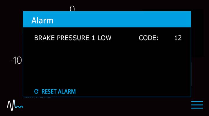
- To reset the alarm, press the Reset Alarm button:

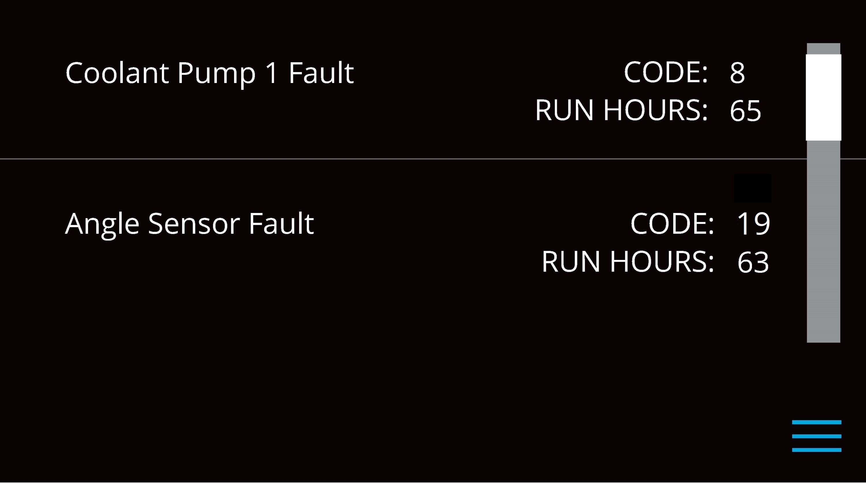
4.6 Alarm History
The ALARM HISTORY page on the Seakeeper application shows the recent alarms and warnings. Alarms trigger a pop-up message to be displayed on the display or Seakeeper App. Warnings will be listed in the alarm history but do not affect Seakeeper operation. The alarms and warnings are in chronological order starting with the most recent. Warnings included in the history page are for issues that do not affect gyro operation.
Press the Menu button ![]() to show the page options and then the ALARM button
to show the page options and then the ALARM button ![]() to show alarm history.
to show alarm history.
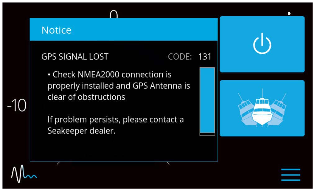
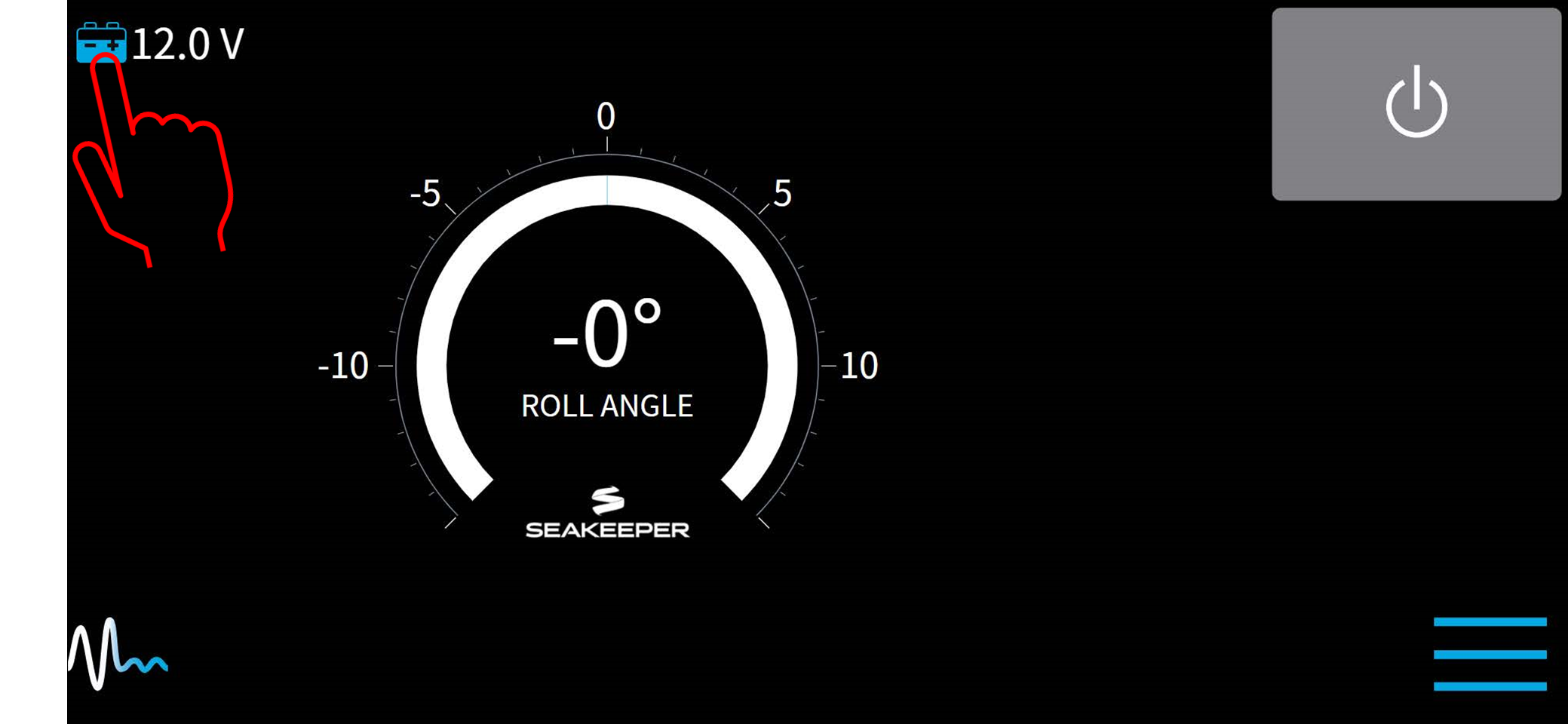
If a GPS signal is lost, a warning message will appear in the Alarm History and a message will appear on the Home Screen, as seen below. The Seakeeper will not spool down, however the precession rate and angle of the sphere will be reduced until GPS signal returns.
5.0 Maintenance
3.3.4 Battery Monitoring
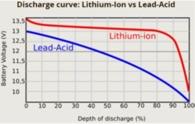
The Seakeeper 4 is equipped with voltage and state of charge (SoC) based battery monitoring logic to accommodate traditional battery chemistries and emerging lithium-ion technology. The default mode is a low voltage protection system using 11.3 VDC as the protection threshold for flooded and absorbed glass mat (AGM) batteries. SOC-based monitoring is enabled when a NMEA 2000 compatible battery monitoring system (BMS) is broadcasting SOC (PGN: 127506, DC Detailed Status) over the NMEA 2000 network and is required for Seakeeper operation with Lithium batteries. The default voltage-based protection is not compatible with lithium batteries due to the discharge characteristics of this battery type.
If powered by a lithium battery, the Seakeeper and BMS must be connected to a common NMEA 2000 network to prevent excessive discharge of the battery bank. An external BMS with a shunt can be used in place of a NMEA 2000 SOC signal, however, the Seakeeper will not provide any battery monitoring functionality. The following guide will explain the functionality of the user interface and menus.
- To access the battery monitoring configuration manager, press and hold the battery icon on the Home screen until the Battery Monitoring Configuration pop-up appears.
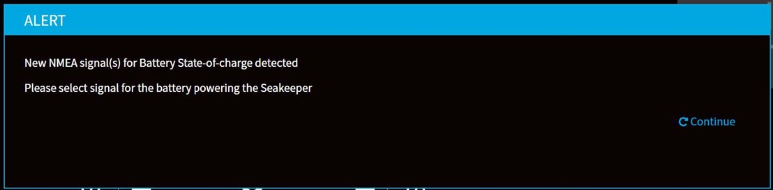
- The Battery Monitoring Configuration will initiate a pop-up after detecting the SoC signal automatically. From this pop-up window, one can also open the Battery Monitoring Configuration by pressing the Continue button.
- Once the Battery Monitoring Configuration manager window appears, press the dropdown menu down arrow and select SoC source from the dropdown menu.
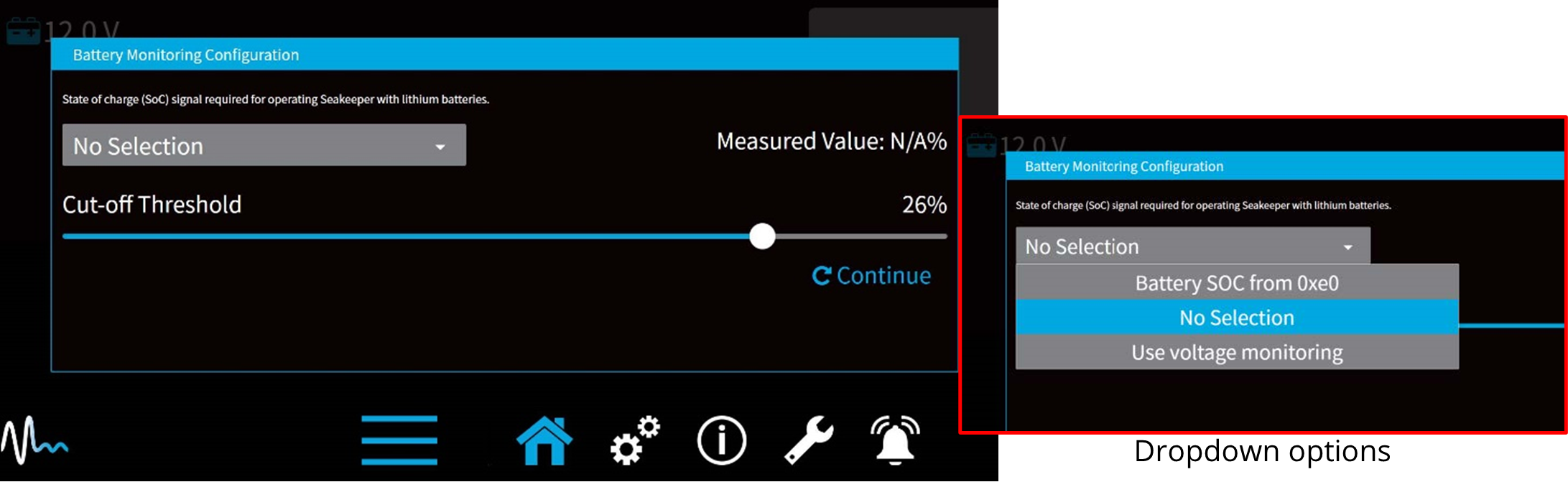
The dropdown options include:
- Battery SOC – This option allows the user interface to monitor the NMEA2000 network for the battery state of charge (required if lithium batteries are used to power the Seakeeper). When selected, the Cut-off threshold slider will determine at what battery charge the Seakeeper begins powering back to conserve battery power. Also, the 5” Touch Display will show battery state of charge.
- No Selection – This is the default setting for the configuration manager. Low voltage protection at 11.3 VDC is used until a different option is selected.
- Use voltage monitoring – This disables SoC logic and uses actual battery voltage to initiate lowering power drawn by the Seakeeper when battery voltage drops to 11.3 VDC on Seakeeper 4.
The Cut-off Threshold Slider controls the level of charge at which the Seakeeper will begin lowering the power it draws. The default setting is 20% charge. The slider allows the selection between 10% and 30% charge state.
5.1 Maintenance Introduction
Seakeeper recommends a regular inspection interval and scheduled maintenance to keep the Seakeeper 4 running trouble-free.
If the Seakeeper is installed in a wet space, efforts should be made to keep the Seakeeper free of salt residue from either condensation or direct exposure to salt spray. If exposed, a regular wipe down with mild soap and water with a rinse will help limit corrosion and keep the Seakeeper assembly in good cosmetic condition. Refer to Seakeeper Care article for details.
If any components of the Seakeeper or its sub-systems will be exposed to environmental temperatures where winterization is necessary for storage, reference Seakeeper Winterization article.
The Seakeeper comes standard with sealant and thread locker on applicable fasteners. When reinstalling all fasteners, use thread locker (Loctite 243 or equivalent) and sealant unless otherwise specified.
Scheduled Maintenance and the replacement of ‘wear’ items are not covered under the warranty. See the warranty limitations and exclusions statement at the link below.
Seakeeper Warranty | Boat Gyro Stabilization Units
Reference Documents:
- TB-90426 – Seakeeper Scheduled Maintenance Plan
- TB-90747 – Seakeeper Annual Inspection
- Seakeeper Winterization Article
- Seakeeper Care Article
Due to remote start capabilities of MFDs, ENSURE power removed from Seakeeper and flywheel at zero RPM at display/MFD app before removing covers.
Hydraulic Hand Pump Kit is required for servicing the brake. Pressure should NOT be relieved unless this tool is available.
5.2 Recommended Scheduled Maintenance Plan
Below is a link to the scheduled maintenance plan. Recommended scheduled maintenance is not covered under warranty.
90426 – Seakeeper Scheduled Maintenance Plan
- The Recommended Scheduled Maintenance should be performed by a SEAKEEPER trained factory technician or trained technician within the Seakeeper Dealer network. Find a local Dealer on our website at www.seakeeper.com/find-us/.
- A Seakeeper technician or Dealer is required to perform a brake service and to replace brake bushings or other brake components. This requires a complete flush, bleed, purge and pressurization of the closed hydraulic system.
- Scheduled Maintenance and the replacement of ‘wear’ items are not covered under the warranty. See the warranty limitations and exclusions statement at the link below.
Seakeeper Warranty | Boat Gyro Stabilization Units
6.0 Warranty and Limit of Liability
6.1 Data Privacy and Warranty
The complete Seakeeper warranty details may be found on the Seakeeper website www.seakeeper.com.
Register your Seakeeper at the Seakeeper Warranty Registration page.
Seakeeper Data Privacy
The Default Data Setting has been activated for your Seakeeper Unit. In compliance with Seakeeper’s Privacy Policy, the Default Data Setting collects pertinent data and information relative to the installed Seakeeper Unit. You are consenting to push such data and information for Seakeeper’s internal usage and for service interventions. You can turn off the Default Data Setting by going to the “Settings Tab” of the Seakeeper application on the boat’s Multifunction Display (MFD).
Seakeeper’s current Privacy Policy indicates that Seakeeper Inc. and all its subsidiaries (collectively “Seakeeper”) collect, store, and use your personal information in connection with and to provide and develop Seakeeper’s products, mobile applications, services, and websites (together the “Service”). Data collected directly from your Seakeeper Unit includes, but is not limited to, the following:
- Boat speed
- Course over ground
- Latitude/Longitude (position)
- Accelerations (fore/aft, up/down, and side/side)
- Angles (roll, pitch, and yaw)
- Rates (roll, pitch, and yaw)
- Seakeeper metrics (System on/off, enclosure position, and faults)
By providing us information or using or accessing the Service you give consent to the processing, use and disclosure of your Seakeeper data and other content (“User Content”). Seakeeper will not rent or sell your information to third parties outside Seakeeper without your consent, except as noted in its Privacy Policy located at https://www.seakeeper.com/privacy-policy.
In addition to some of the specific uses of information we describe in our Privacy Policy, we may use information that we receive to:
- Manage your customer relationship and provide you with customer support
- Help you efficiently access your information after you sign in
- Provide, improve, test, and monitor the effectiveness of our Service
- Develop and test new products and features
- Diagnose or fix technology problems
- Enforce our terms and conditions
- Manage our business
- Perform functions as otherwise described to you at the time of collection
To set or change your Default Data Setting preference to deny sharing data, perform the following procedure.
- At your MFD display, OPEN the Seakeeper application.
- NAVIGATE to the Settings page (gears icon).
- PRESS AND HOLD the gears icon again until a second screen appears (Figure 4).
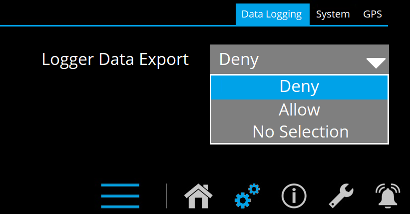
- SELECT the Data Logging tab.
- SELECTDeny option from the dropdown menu of Logger Data Export.
Seakeeper Standard Models
This warranty starts upon the installation of the Product, and the warranty period is for the shorter of the following periods:
- Twenty-four (24) months from purchase date of a vessel on which the Product is installed;
- Twenty-four (24) months from date the Product is installed on an existing vessel (refit); or
- Two thousand (2000) operating SEA hours, subject to verification and confirmation by SEAKEEPER.
Exclusions
Any installation, repair or any handling of the Product shall be done only by an authorized person trained and explicitly authorized in writing by SEAKEEPER.
This warranty shall be void and not apply to or resulting from:
- ANY UNAUTHORIZED MODIFICATION OF THE PRODUCTS AS SHIPPED WILL RESULT IN VOIDING THIS WARRANTY.
- An application or installation method not approved by Seller, including improper or inadequate site preparation, faulty installation, handling during maintenance or otherwise, if any, by the Customer, as well as to defects attributable to loading/shipment/delivery of the Product or any other defect or damage not attributable to SEAKEEPER.
- Defects resulting from Customer’s or any third-party interface of equipment, hardware or software if installed, connected, or loaded into and/or onto the Product.
- Misuse, operator error or fault caused by the failure of an external unit (i.e., Sea Water pump, Ships power supply).
- Any negligent or willful misconduct.
- Excessive exposure to water (salt or fresh) including submersion (partial or full).
- Acts of Nature such as, but not limited to, fire, flood, wind, and lightning.
- Improper use or operation of the vessel.
- Failure of the Customer to strictly comply with any of the following requirements:
- Operation and Maintenance according to the guidelines and recommendations specified in the SEAKEEPER Operation Manual.
- Proof of such compliance shall be provided upon request.
- Operation and Maintenance according to the guidelines and recommendations specified in the SEAKEEPER Operation Manual.
Warranty Activation
A Warranty Registration must be fully completed and sent to SEAKEEPER for review, approval and registration upon delivery of the vessel to the first retail Customer. Warranty registration and expiration date confirmation can be achieved by providing SEAKEEPER, a copy of the original bill of sale, purchase agreement, Customer’s name, address and SEAKEEPER Product Serial Number along with current RUN / SEA hours to SEAKEEPER’s warranty registration department within thirty (30) days of purchase.
For removal of doubt, it is clarified that the activation date shall in no event affect the warranty period set forth herein.
6.2 Limitation of Liability
NOTWITHSTANDING ANYTHING CONTAINED HEREIN TO THE CONTRARY, SEAKEEPER, INC., SHALL NOT BE LIABLE FOR ANY SPECIAL, PUNITIVE, INCIDENTAL, INDIRECT OR CONSEQUENTIAL DAMAGES INCLUDING, BUT NOT LIMITED TO, LOST PROFITS, ARISING OUT OF THE PERFORMANCE, DELAYED PERFORMANCE OR BREACH OF PERFORMANCE OF THIS ORDER REGARDLESS OF WHETHER SUCH LIABILITY IS CLAIMED IN CONTRACT, EQUITY, TORT OR OTHERWISE, EVEN IF ADVISED OF THE POSSIBILITY OF SUCH DAMAGES. SEAKEEPER’S OBLIGATION IS LIMITED SOLELY TO REPAIRING OR REPLACING (AT ITS OPTION AND ONLY AS SET FORTH HEREIN), AT ITS APPROVED REPAIR FACILITY, ANY GOODS OR PARTS WHICH PROVE TO SEAKEEPER’S SATISFACTION TO BE DEFECTIVE AS A RESULT OF DEFECTIVE MATERIALS OR WORKMANSHIP, IN ACCORDANCE WITH SEAKEEPER, INC.’S STATED WARRANTY. IN NO EVENT SHALL SEAKEEPER’S CUMULATIVE LIABILITY EXCEED THE TOTAL PURCHASE PRICE SETFORTH IN THIS ORDER. CUSTOMER HOLDS HARMLESS SEAKEEPER AND INDEMNIFIES SEAKEEPER FOR ANY ACT OR OMISSION TO ACT THAT VOIDS THE LIMITED WARRANTY OR OTHERWISE BREACHES CUSTOMER’S OBLIGATIONS PURSUANT TO THE TERMS AND CONDITIONS OF SALE.
The terms and conditions of this warranty are the entire agreement between the Parties relating to the warranty obligations of SEAKEEPER to the Products. There are no other express or implied terms or conditions of this warranty.
7.0 Specifications and Summary
| Specification | Seakeeper 4 |
|---|---|
| Rated RPM | 8,250 RPM |
| Angular Momentum at Rated RPM | 4,000 N-m-s |
| Anti-Rolling Torque at Rated RPM | 10,427 N-m |
| Spool-up Time to Rated Speed | 60 minutes (8,250 RPM) |
| Spool-up Time to Stabilization | 34 minutes (6,188 RPM) |
| Spool-up Power DC Motor | 1,050 Watts Max |
| Operating Power DC (Sea state dependent) | 550 – 1,050 Watts |
| Drive Power Input | 12 VDC @ 88 Amps (max) |
| Control Power Input | 12 VDC @ 15 Amps Max |
| Seawater Power Input | 12 VDC @ 15 Amps Max |
| Seawater Supply to Heat Exchanger | 2.5 GPM (9.5 LPM) minimum 4 GPM (15.2 LPM) maximum |
| Ambient Air Temperature | 32˚ – 140˚F (0 – 60˚C) |
| Weight | 746 lbs (338 kg) |
| Envelope Dimensions | 26.56 L x 28.05 W x 20.98 H (inches) .675 L x .713 W x .533 H (meters) |
| Noise Output | < 72 dBC at 1 meter |
Arrangement
The Seakeeper 4 consists of the Flywheel, Enclosure, Foundation, Electronics, Brake, Cooling, and Cover Subsystems.
Installation Location
The Seakeeper is a torque device and does not have to be installed in a specific hull location or on the centerline. However, the Seakeeper should not be installed forward of the longitudinal center of gravity to minimize high acceleration loading due to hull/wave impacts during operation at high speed or in large waves.
Mounting Dimensions
See Drawing No. 90726 – Seakeeper 4 Bolt-In Installation Details.
Loads
The installer is responsible for designing the foundation to which the Seakeeper is attached and for ensuring that this foundation can safely transfer the concentrated Seakeeper loads from the frame to the adjacent hull structure. Loads that the Seakeeper imposes on the hull structure are explained on Drawing No. 90XXX – Seakeeper 3.75 Bolt-In Installation Details; these loads do NOT include vessel motion accelerations, such as vertical slam loads which can be high for higher speed vessels.
Cooling
The Seakeeper bearings, Motor Drive Box, and hydraulic manifold are cooled by a closed water / glycol mix cooling loop that incorporates a seawater heat exchanger. The installer is responsible for providing 2.5 – 4 GPM (9.46 – 15.14 LPM) raw water at ambient sea temperature and a maximum pressure of 20 psi (1.4 bar) to the heat exchanger.
Electrical
The installer is responsible for supplying 12 VDC at 100 A service to the Motor Drive Box, 12 VDC at 15 A service to the Seakeeper Control System, and 12 VDC at 15 A service to the Seawater Pump. Separate circuit breakers should be used for each Motor Drive Box in multiple Seakeeper installations. Similarly, separate circuit breakers should be used for each Seakeeper Control System and Seawater Pump in multiple Seakeeper installations.
Operator Controls
A compatible MFD or a 5″ Touch Display is used to start, operate, monitor, and shutdown the Seakeeper from the helm. The operator may also use the local ConnectBox interface on the Seakeeper 4 to start and shutdown the Seakeeper.
Performance
Reduction of boat roll is a function of the boat’s displacement, transverse metacentric height (GMT) and hull damping as well as the operating conditions (speed and heading with respect to waves) and sea state. The Seakeeper controller regulates the active hydraulic brake to ensure the Seakeeper’s anti-roll torque is maximized regardless of hull characteristics or operating conditions.
Alarm and Monitoring
Sensors, alarms and shutdowns are provided to allow unattended operation. Sensors measure Seakeeper and drive temperatures, vacuum pressure, gimbal angle, brake pressure, and ship motion. The Seakeeper controller sends sensor values and alarm information to the display and also locks the brake and shuts down the motor drive in the event of an alarm condition. Seakeeper operating history during faults or alarms is recorded in the controller’s memory for subsequent recall if service is needed. Seakeeper may access the Seakeeper’s software to gather run hours, bearing loading, and hull slamming information.
Safety
The brake automatically locks the Seakeeper so it cannot generate excessive anti-rolling torque loads in the event of a system fault or alarm, loss of electrical power or loss of brake pressure. The brake can be locked from the Display or by shutting off AC and DC power at the supply breakers.
8.0 Revision History
| REVISION | DESCRIPTION | DATE |
| 1 | Initial release. | 09NOV2023 |