Seakeeper 4 Operation Manual (90761-1)
4.0 Power Failures, Alarms, and Troubleshooting
4.1 Power Failures, Alarms, and Troubleshooting Introduction
The Seakeeper 4 has safety features, such as alarms and warnings, that pop-up on the Seakeeper
Application and are signaled on the ConnectBox to protect the Seakeeper as well as the vessel. The brake can be locked from the Application, ConnectBox or by shutting off DC power at the supply breakers, preventing the Seakeeper from precessing.
4.2 Power Failures
The Motor Connections should not be touched when the Seakeeper is Powered on, or the motor is running. This voltage hazard exists even if the flywheel is coasting down, and the supply voltage has been shut off.
________________________________________________________________________________________________
The flywheel must be at Zero (0) RPM and DC input power disconnected for at least 10 minutes prior to any service work on the Seakeeper.
In the event of a power failure, the brake automatically locks the Seakeeper so it cannot generate anti-rolling torque loads. When a power failure occurs, it is important to identify the three sources of power to the Seakeeper 4:
- 12 VDC high current powers the Motor Drive.
- 12 VDC low current powers the Seakeeper control electronics, ConnectBox, and optional 5″ Touch Display.
- SW Pump 12 VDC input powers the seawater cooling pump.
Power is supplied via cables which are shown on Drawing No. 90699 – Seakeeper 4 / 4.5 Cable Block Diagram.
4.3 12 VDC High Current Failure
If the 12 VDC high current is disconnected during operation, a notification screen will indicate “High Current DC Voltage Low”. If the failure is not corrected within two minutes, a “High Current DC Voltage Low” alarm will occur. The brake will lock.
- Verify the boat’s circuit breaker or fuse supplying +12 VDC high current has not tripped or blown.
- When +12 VDC high current is restored, the display will power up, the Splash Screen will appear, and then the Home Screen will appear.
- Press Power On/Off button
 . The progress bar will appear and indicate flywheel speed. When the flywheel is at minimum operating speed, the Stabilize button will appear so stabilization can be turned on. This may take up to 30 minutes, depending on the speed of the flywheel when the +12 VDC high current is turned back on.
4.4 12 VDC Low Current or SW Pump Power Failure
If the 12 VDC low current is disconnected during operation, the display will be blank, flywheel speed will decrease, and the Seakeeper will be turned off (no stabilization).
- Verify the boat’s circuit breaker or fuse supplying +12 VDC low current has not tripped or blown.
- When +12 VDC low current is restored, the display will power up, the Splash Screen will appear, and then the Home Screen will appear.
- Press Power On/Off button . The progress bar will appear and indicate flywheel speed. When the flywheel is at minimum operating speed, the Stabilize button will appear so stabilization can be turned on. This may take up to 30 minutes, depending on the speed of the flywheel when the +12 VDC low current is turned back on.
If SW Pump input 12 VDC power is disconnected during operation, the SW Pump will fail to provide cooling seawater flow when required. The resulting high temperatures would result in the Seakeeper being turned off (no stabilization).
- Verify the boat’s circuit breaker or fuse supplying +12 VDC SW Pump power has not tripped or blown.
- When +12 VDC SW Pump power is restored, reset any alarm and continue Seakeeper operation.
4.5 Alarms
Sensors, alarms, and shutdowns are provided to allow unattended operation. Sensors measure drive temperatures, gimbal angle, brake pressure, and vessel motion. The Seakeeper controller sends sensor values and alarm information to the display and locks the brake and shuts down the motor drive in the event of an alarm condition. Seakeeper operating history during faults or alarms is recorded in the controller’s memory for subsequent recall if service is needed. Seakeeper and Seakeeper Dealers may access the Seakeeper’s software to gather run hours, bearing loading, and hull slamming information.
The operator should physically examine the Seakeeper following an alarm. Continuing to reset alarms without service intervention can result in damage or personnel injury.
NOTE: the Seakeeper 5” Touch Display or the MFD to identify and address the alarm. The alarm will not clear until the operator presses the Reset Alarm button, AND the alarm condition is no longer present. The operator can then press the POWER button again to resume Seakeeper operation.
- A view of a typical Alarm screen.
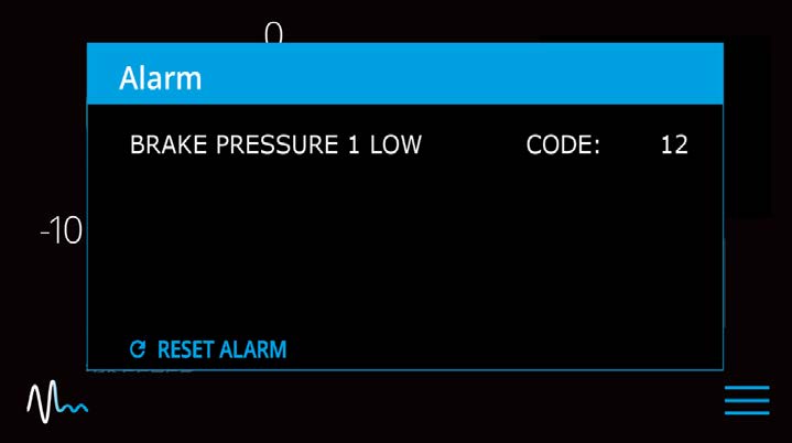
- To reset the alarm, press the Reset Alarm button:

4.6 Alarm History
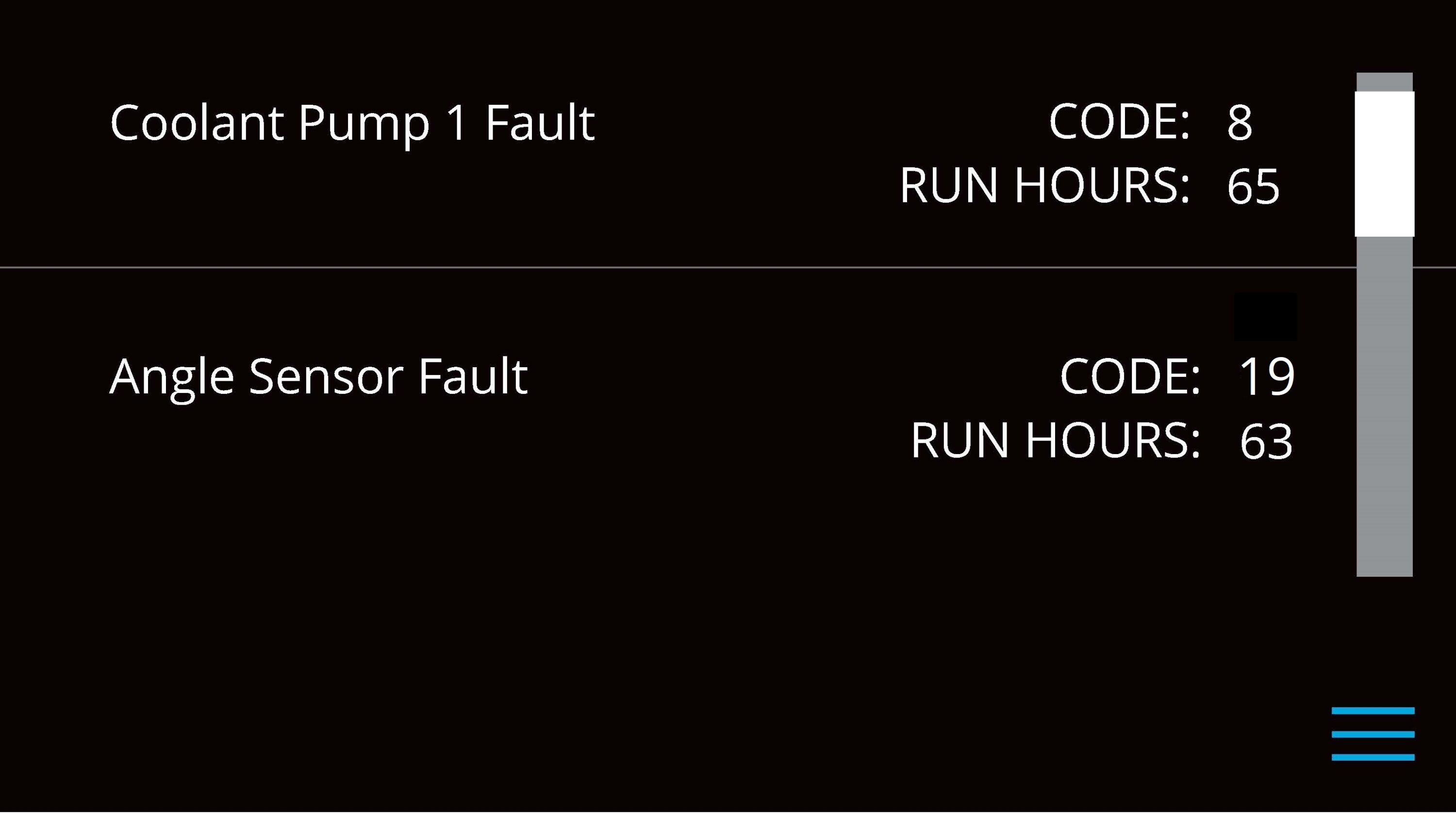
The ALARM HISTORY page on the Seakeeper application shows the recent alarms and warnings. Alarms trigger a pop-up message to be displayed on the display or Seakeeper App. Warnings will be listed in the alarm history but do not affect Seakeeper operation. The alarms and warnings are in chronological order starting with the most recent. Warnings included in the history page are for issues that do not affect gyro operation.
Press the Menu button ![]() to show the page options and then the ALARM button
to show the page options and then the ALARM button ![]() to show alarm history.
to show alarm history.

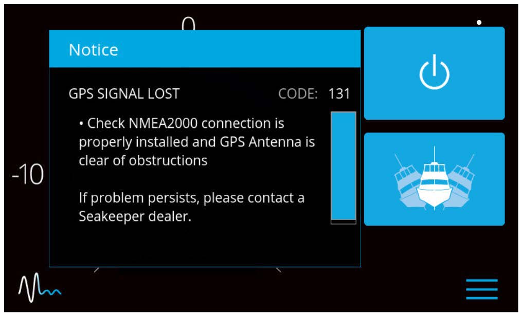
If a GPS signal is lost, a warning message will appear in the Alarm History and a message will appear on the Home Screen, as seen below. The Seakeeper will not spool down, however the precession rate and angle of the sphere will be reduced until GPS signal returns.