Configuration Instructions for Legacy Software
Commissioning Instructions for Legacy Software
1. Introduction
Updated 09/04/2024
Following installation, the Seakeeper Ride system must be configured prior to operation. This process is performed by the Original Equipment Manufacturer (OEM/boat builder) or a professional Seakeeper certified installer if they performed the installation.
Note: Scan the QR code below to access Seakeeper Ride BILT 3D instructions. BILT App will assist in familiarization with the Seakeeper Ride components and includes a specific section for commissioning.


ATTENTION! Changing these critical settings can render the system non-functional and create an unsafe operating condition. Please proceed only if you have read and understand this manual in full.
ATTENTION! Advanced Mode configurations should only be changed under extenuating circumstances, such as replacing system components or if an incorrect calibration has been confidently diagnosed.
For Seakeeper Ride systems installed by end users, follow the steps below to commission your new system. The full procedure should take approximately 10 minutes if the boat is in a proper location before starting.
After following both the Mechanical and Electrical installation instructions, begin commissioning by ensuring the following:
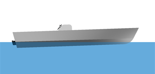
- The boat is on an even keel (level port to starboard)
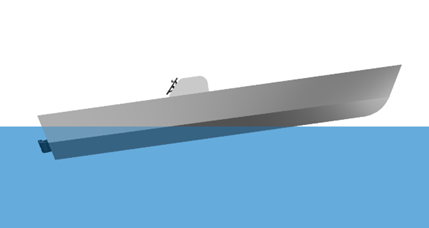
- The boat is trimmed level (no excess bow down or stern down angle)
- GPS has consistent satellite signal
- You have access to Controllers (If the boat is in the water this may not be possible, and therefore the boat may need to be trailered for the full procedure)
- You are aware of the cable side of the Actuators (example: port side Actuator Cable is in the port cable entry)
- You have access to the Distribution Module for unplugging and re-plugging in Controllers
- You have access to the MFD and optional Keypad
- You have access to circuit breakers
- You have access to the engine key switch
- No unnecessary persons are on the vessel
2. Software Module Switches
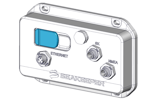
For Seakeeper Ride to connect properly to the Multifunction Display (MFD), the switches on the Software Module must be in the correct positions. Access the switches by removing the rubber covering on the upper left side of the Software Module.
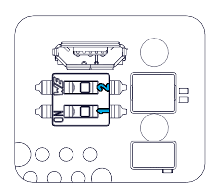
Do not move Switch 2. Follow the table below to configure Switch 1 based on the MFD brand. The ‘on’ position is to the left.
| Garmin, Raymarine, Furuno | Switch 1 Off |
| Simrad, Lowrance, B&G, | Switch 1 On |
3. First Installation
The following instructions are for Legacy Software Version 2023.4.6 and older. If you have the ability to do so, please update as soon as possible for increased performance and better user interface. You can find software and instructions here https://ride.seakeeper.com/support/software-updates/
If you cannot update your software, please continue on for step-by-step instructions on Commissioning older Software.
The Advanced Mode, shown below, will remain available for users that have not updated their Seakeeper Ride system prior to September 1, 2023.
These settings all must be entered and completed in preparation for using Seakeeper Ride. The following information details each system status screen item, what they mean and how they affect the Seakeeper Ride system.

ATTENTION! Changing these critical settings can render the system nonfunctional and create an unsafe operating condition. Please proceed only if you have read and understand this manual in full.
Note: Please review the Electrical Installation Manual (Seakeeper Ride | Electrical Installation Manual) and BILT App QR code (below) for precise details on the Software Module location for best performance.


Note: The speed of the boat, GPS connection, and the system being in Auto or Manual mode will all influence how Seakeeper Ride behaves. Even if Seakeeper Ride is set up correctly, the Controllers may have limited range based on these factors. Refer to the table below for more information and see the Seakeeper Ride Operation Manual Section 2.1 and Section 2.2 for home screen controls.
If the Seakeeper Ride system has already been commissioned previously, then please follow the Section 4 – Service Menu Items steps to access the Service Menu Items.
4. Enter Advanced Mode
The following instructions for ‘Advanced Mode’ will remain available for users that have updated their Seakeeper Ride system prior to September 1, 2023. Please update Seakeeper Ride system to the latest Software Update possible at the link listed here. https://ride.seakeeper.com/support/software-updates/
Access Advanced Mode to configure the system components. Configuration will program all components to function together as a complete system. This step must be performed on the first start of the Seakeeper Ride System to make the system operational. Only under extenuating circumstances will the Advanced Mode need to be accessed following the first start. The operator will be able to access configuration settings for:
- Angle Calibration
- IMU Orientation
- Controller Configuration
ATTENTION! The Advanced Mode screen is only to be used when commissioning the Seakeeper Ride system or if configuration was done incorrectly.
- From the Home screen press Settings
 in the bottom right of the MFD.
 - Select the Install screen in the top right.

- Select Advanced Mode.

- You will be prompted twice to determine if you wish to proceed. Select Continue both times to access the configuration home screen.
- Even if the Configuration Condition shows Satisfied, the configuration must be completed before the Seakeeper Ride system is operational. See the following steps below.

- To begin the Configuration Mode, select Enabled.
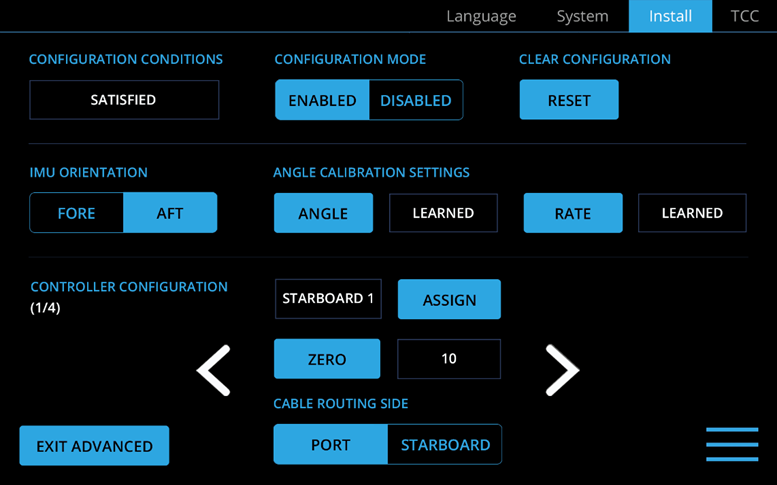
- The Advanced Settings screen will appear.
Note: Both options must be selected before choosing the option you want in order for the system to recognize your selection.
5. Angle Calibration
Angle calibration adjusts the sensors in the Seakeeper Ride system to match the detected horizon, providing a target attitude used during Auto Mode operation. Once the Seakeeper Ride is in operation, the system will adjust the boat’s attitude to match the horizon as calibrated during this step. It is critical that the boat is on an even keel with no excess bow or stern trim during this step. Because of the system’s precision, this step takes up to 1 minute to complete and will directly affect the performance of the system.
Note: Excess motion during this step disrupt calibration. If this is performed on water, it must be especially calm. Movement of passengers on board the boat is unacceptable.
There are two ways to perform the angle calibration, both of which will provide the same result. Follow the steps the steps below to use either the Advanced Settings screen or the Install Screen to complete the angle calibration.
Advanced Settings Screen Angle Calibration
- While in the Advanced Settings screen, select Angle under Angle Calibration Settings.

- Wait 60 seconds for the computer to calibrate. Select Rate. Wait an additional 60 seconds for the computer to calibrate.
Install Screen Angle Calibration
- From the Home Screen, press the Settings icon on the bottom right of the display.
- Select the Install screen in the top right of the display.
- Select Angle Calibration.

- You will be asked if you wish to proceed. Press Continue.
- Selecting Angle Calibration again will provide another prompt asking if you wish to proceed. Press Continue again.
- The calibration will begin. Once completed, the Install screen will reappear.
6. IMU Orientation
Note: Both options must be selected before choosing the option you want in order for the system to recognize your selection.
The Inertial Measurement Unit (IMU) provides angle and speed information to the Seakeeper Ride system to allow for dynamic damping of the boat’s motions. The IMU Orientation programs the system to be aware of the IMU’s relation to the boat.

The IMU selections are as follows:
- Fore orientation indicates the logo on the Software Module faces the bow of the boat.
- Aft orientation indicates the logo on the Software Module faces the stern of the boat.
7. Controller Configuration
Controller Configuration will program the Software Module to determine three (3) critical items:
- The side of the boat the Controller is on
- The fully retracted position
- The direction the Controller should move
Note: Both options must be selected before choosing the option you want in order for the system to recognize your selection.
Follow these steps to complete the Controller Configuration:
- Unplug both Controllers from the Distribution Module.
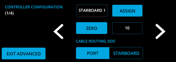
- Plug in the port side Controller to the Distribution Module in either of the Ampseal ports.
- Select Assign.
- In the pop-up window, select Port 1.
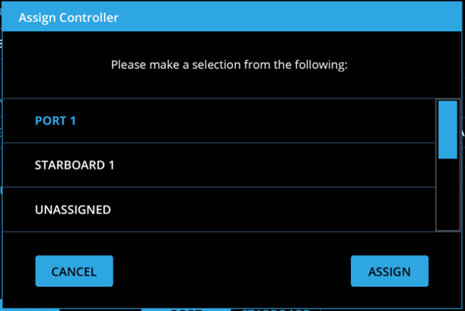
- Select Assign.
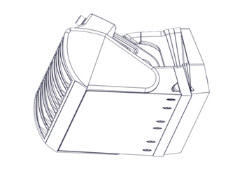
- Move the Blade such that it is flush with the Seal Plate (right).
- Select Zero.
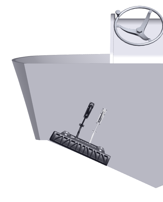
- Select the Cable Routing Side based on if the Actuator Cable is on the port or starboard side of the Controller.
Example: The port side Controller is shown in the figure. The black cable is routed on the port Cable Routing Side. If the position of the white cable was used, the correct selection would be starboard for the Cable Routing Side.
- Unplug the port side Controller from the Distribution Module.
- Repeat steps 2-9 for the starboard Controller. Use the arrows on the screen to alternate between port and starboard after plugging in the Controllers.
- Plug both Controllers into the Distribution Module. To ensure the Controllers are properly connected, gently pull on the cables after plugging them in.
- Once complete, allow 30 seconds for the system to save all data.
8. Exiting Advanced Mode
To exit advanced mode:
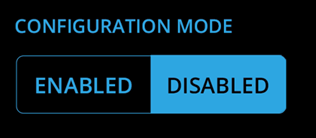
- Under Configuration Mode, select Disabled
- Select Exit Advanced.
Rebooting the system after any configuration to make sure all settings are saved and applied.
- Turn the engine key off.
- Wait for at least 30 seconds.
- Turn the engine key on.
9. Testing the System
Once the system has been configured, test that the system is operating correctly. While testing the system, make sure the boat is stationary and has GPS connection. Testing is best done with the boat out of the water, allowing the Controllers to be seen more clearly. If the Seakeeper Ride system does not perform as indicated in any of these steps, return to the previous sections and repeat the associated procedures as necessary.
Note: Pressing the left and right directional arrows move the Blade, blue fill bar, and Keypad lights on the opposite side. For example, pressing the left, or port side, arrow will change the starboard side blue fill bar.
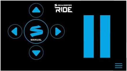
- Enter Manual Mode by pressing the Seakeeper Logo in the center of the directional arrows on the Home Screen of the display or the Keypad.
- Look over the transom of the boat to visually confirm the Controller’s Blades are fully retracted and flush with the Seal Plate.
- Use the up directional arrow to fully deploy the Blades. The blue bars on the screen should be filled in with blue completely. Look over the transom of the boat to verify the Controller Blades have deployed completely.
- Use the down directional arrow to retract the Blades completely.
- Press the right directional arrow until the port side blue bar fills in completely.
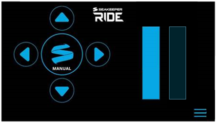
- Visually confirm that the port Controller’s Blade is deployed completely.
- Repeat steps 5-6 for the left directional arrow corresponding to the starboard Controller.
The Seakeeper Ride system commissioning is now complete. Please refer to the Quick Start Guide to begin using the Seakeeper Ride system.
Note: The speed of the boat, GPS connection, and the system being in Auto or Manual mode will all influence how Seakeeper Ride behaves. Even if Seakeeper Ride is set up correctly, the Controllers may have limited range based on these factors. Refer to the table below for more information, and see the Seakeeper Ride Operation Manual Section 2.1 and Section 2.2 for home screen controls.
| Auto Mode | Manual Mode | |
|---|---|---|
| Speed (with GPS signal) | ||
| 0-10 mph | Blades can be moved fully together by trimming with the up and down directional arrows. The left and right directional arrows will apply a trim to the system but will not cause the Blades to move at these speeds. The Blades will not move automatically. | Blades can be moved fully with the directional arrows. |
| 10+ mph | Blades will deploy automatically based on movement of the boat and the TCC. At higher speeds, the Blades will deploy less. Blades can also be manually trimmed with the directional arrows. | Blades can be moved fully at lower speeds and will allow less movement at higher speeds. |
| GPS | ||
| Connected, Good Signal | Blades will deploy as described above in the ‘Speed’ section. | Blades can be moved to the maximum range allowed by the speed. |
| No Signal | Auto Mode will be disabled. Fault will be shown on screen. | Blades can be moved with the directional arrows up to 25% deployment regardless of speed. |
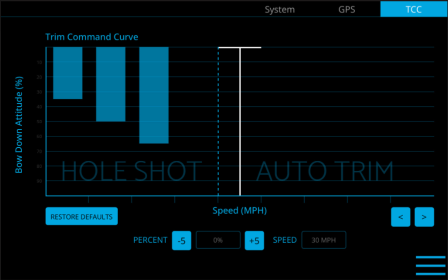
10. Trim Command Curve (TCC)
The Trim Command Curve (TCC) allows the operator to set a preferred trim at speeds of 10-50 mph in 5 mph increments. This important feature allows the boat to get on plane significantly faster by deploying the Blades when accelerating. The TCC additionally allows the operator to adjust the attitude of the bow by setting preferred Blade deployment at cruise speeds.
The default TCC setup is designed to work well for all boats equipped with Seakeeper Ride. If Seakeeper Ride is being commissioned at an OEM boat builder and a desired TCC setup is known for a particular model of boat, those settings may be applied at this time. Otherwise, it is recommended to wait to customize the TCC until testing the performance of the boat in the water.
For more information on the TCC and instructions on customization, see Section 3.3 of the Seakeeper Ride Operation Manual.
11. Troubleshooting
If Seakeeper Ride does not operate correctly when testing the system in Section 10 or if the commissioning process is unable to be completed because of a persisting issue, refer to the Seakeeper Ride Troubleshooting Guide for help. Reviewing and correctly following one or more of the previous commissioning sections will often resolve the issue. However, there may be issues resulting from an incorrect electrical installation, which could include, a loose wire, incorrect wiring, missing components, etc. Visit the tables in the Seakeeper Ride Troubleshooting Guide to help identify possible causes of the issue and find the solution.