Operation Manual (PhasedOut20250429)
Operation Manual
1. Safety Notices
Updated 08/14/24
Responsibility
WARNING! Seakeeper Ride is not intended, nor should it be expected, to alleviate or replace the captain’s control and safe operation of the boat. The captain must, at all times, be in control and operate the vessel in a safe manner.
Seakeeper Ride actively records motion data from your boat. This data is stored locally and is not remotely accessible or monitored by Seakeeper.
2. User Interface
User Interface Introduction
To better operate and utilize the Seakeeper Ride system, please familiarize yourself with the operator interface as detailed in this section.
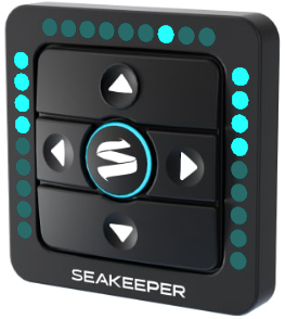
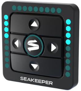
Seakeeper Ride requires a connection to a Seakeeper compatible multifunction display (MFD) for control of the system. Additionally, it can be adjusted with an optional Keypad. The MFD application contains complete system information, while the Keypad provides a quick reference and operator inputs that are always available.
2.1. Home | Auto Mode
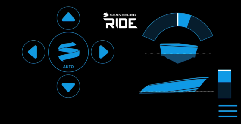
After the Seakeeper Ride application has initialized, the application home screen will be displayed. The home screen will appear different depending on whether the system is in Auto Mode or Manual Mode. The system will be in Auto Mode by default.
1
2
3
4
5
6
7
8
- Auto / Manual Button
- Up Directional Arrow
- Left Directional Arrow
- Right Directional Arrow
- Down Directional Arrow
- Heel Command Indicator
- Trim Command Indicator
- Menu
1
2
3
- Heel Command Indicator
- Port Trim Indicator
- Starboard Trim Indicator
Auto / Manual Button
The button in the middle of the directional arrow pad allows the user to toggle between Auto Mode and Manual Mode. The ring in the center of the Keypad will glow when in Auto Mode.

Warning: Please exercise caution while using Seakeeper Ride in Auto Mode. High speed turns with the Seakeeper Ride system may result in loss of vessel control. Reduce speed before attempting to perform any high speed maneuver. Seakeeper Ride is not intended, nor should it be expected, to alleviate or replace the captain’s control and safe operation of the boat.
Heel Command Indicator
This gauge shows the boat’s attitude relative to the keel, indicating whether the vessel is leaning to port or starboard. The white line marker indicates the center position, in which the boat is on an even keel. The blue bar fills in the arc as the arrows are pressed. If the right arrow is pressed, the blue bar fills in the arc to the right of the white line marker, as shown above, and vice versa. At even keel, no blue bar would be visible.
Note: Heel Indicator does not show when boat is traveling less than 10mph.
Trim Command Indicator
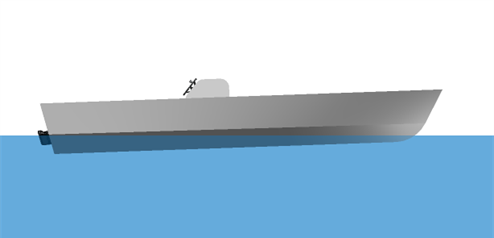
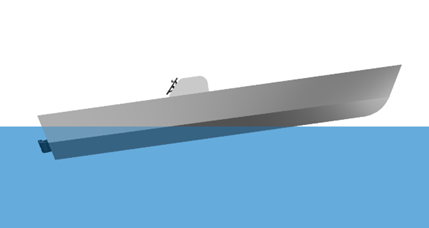
This gauge shows the boat’s pitch, indicating the attitude of the bow. The white line marker indicates the bow positioning the system is holding based on the Trim Command Curve found in the system settings. More information can be found on the Trim Command Curve in Section 3.3. The trim settings may change based on speed, which would change the position of the white line marker within the gauge.
The operator can use the up and down arrows to adjust the bow’s attitude further up or down from the automatic trim setting. The blue bar will move upward from the white line when the bow is commanded further up from the automatic setting. The blue bar will extend downward from the white line when the bow is commanded down further from the automatic setting.
Up & Down Directional Arrows
The operator can use the up and down arrows to adjust the bow’s attitude further up or down from the automatic trim setting. This will be reflected in the Trim Command Indicator. Pressing the up arrow will lower the bow and pressing the down arrow will allow the bow to rise.
Left & Right Directional Arrows
The operator can use the left and right arrows to force the boat to lean to either port or starboard, respectively. This will be reflected in the Heel Command Indicator.
Menu Button
When the Menu button is pressed, the menu bar will appear or disappear at the bottom of the display.
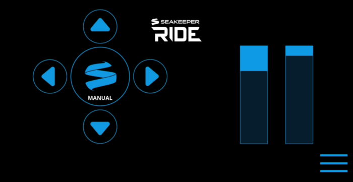
2.2. Home | Manual Mode
In Manual Mode, the operator is in direct control of the Controllers. The system will not actively respond to waves, wakes, and other forces, and the Blades will remain in the position set by the operator via the MFD or Keypad. The operator inputs are indicated by illuminated LED lights on the optional Keypad or in the gauges on the MFD display.
1
2
3
4
5
6
7
8
- Auto / Manual Button
- Up Directional Arrow
- Left Directional Arrow
- Right Directional Arrow
- Down Directional Arrow
- Port Command Indicator
- Starboard Command Indicator
- Menu
1
2
- Port Command Indicator
- Starboard Command Indicator
Auto / Manual Button
The button in the middle of the directional arrow pad allows the user to toggle between Auto Mode and Manual Mode.
Port and Starboard Command Indicators
The Command Indicators show how far each Controller Blade is deployed. If the Port Command Indicator is filled in blue, the port side Controller Blade is deployed fully, which will cause the boat to keel to the starboard side, and vice versa.
Up & Down Directional Arrows
Pressing the up and down arrows in Manual Mode will move the Controller Blades up and down together. Pressing the up arrow will lower the bow and pressing the down arrow will allow the bow to raise. The blue bars in the Command Indicators will move correspondingly.
Left & Right Directional Arrows
The left directional arrow moves the starboard side Controller Blade down, causing the boat to heel to the port side. The right directional arrow moves the port side Controller Blade down, causing the boat to heel to the starboard side. The blue bars in the Command Indicators will move to match the position of the Blade on that side. If there is a command present on one side and the opposing arrow is pressed, the system will level out by bringing the Controller Blades closer to one another.
Menu Button
When the Menu button is pressed, the Menu bar will appear or disappear at the bottom of the screen.
2.3. The Navigation Bar
The navigation bar is used to navigate between pages. The selected page is highlighted in blue on the navigation bar.

Home
On the Seakeeper Ride Home page, the operator will be presented with the directional arrows, the Auto/Manual button and graphic indicators based on the mode selected. Refer to the previous sections for more details on the Home Screen.
Settings
The Settings page allows for adjustment to the System, Install, and Trim Command Curve (TCC). The selection of each of the screens are in the top right-hand corner of the screen once on the Settings page.

System
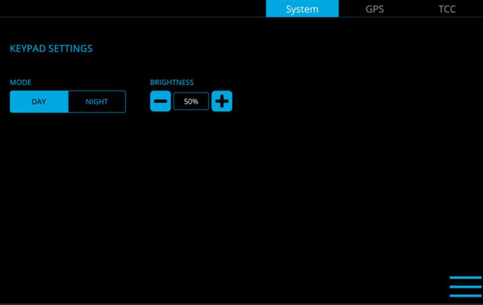
The System page allows the operator the ability to adjust the Keypad settings for day or night display mode and brightness. This will adjust the brightness of the Keypad. When on this screen the operator can select the + button to increase the brightness and the – sign to decrease the brightness. The percentages chosen are different for Day and Night. Once both day and night have been set and they are clear and visible, select the 3 line icon on the bottom right, then the home icon, to return to the main menu of the Seakeeper Ride app.
GPS
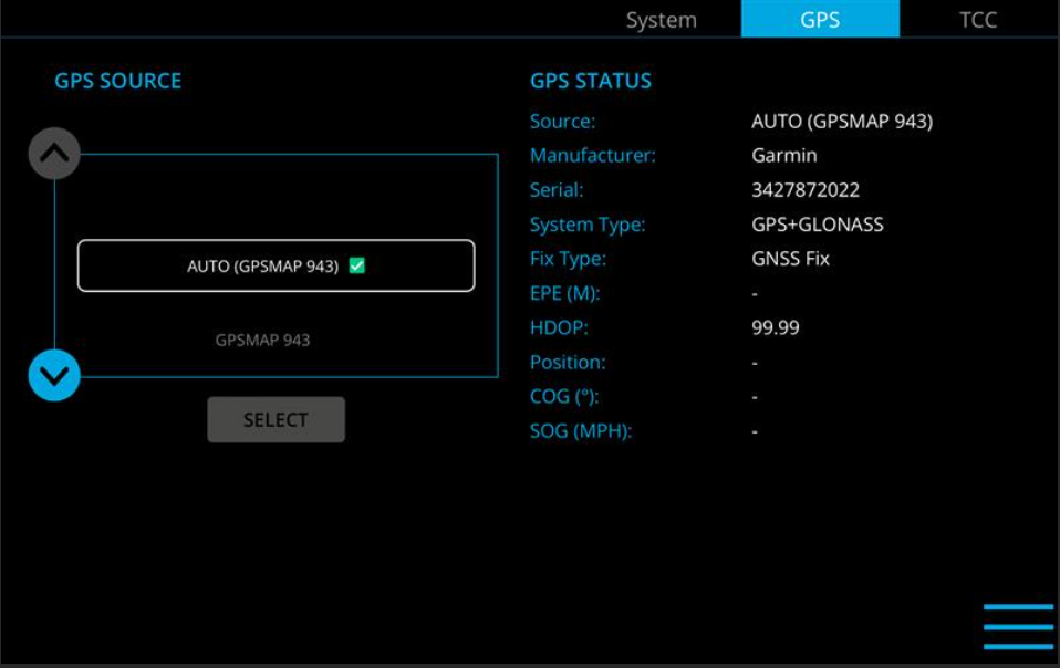
The GPS page allows the operator to choose a GPS source and specific information about the GPS that is chosen. The GPS source will show the GPS manufacturer currently selected and other live data GPS statuses. The GPS source is chosen by determining which GPS has the strongest signal without interruptions and lowest EPE and HDOP.
Trim Command Curve
The Trim Command Curve (TCC) is covered in detail in Section 3.3. Please read the full Operation Manual carefully before making changes to the Trim Command Curve.
Info
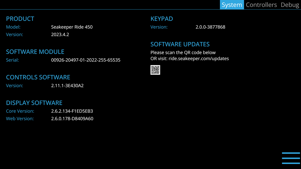
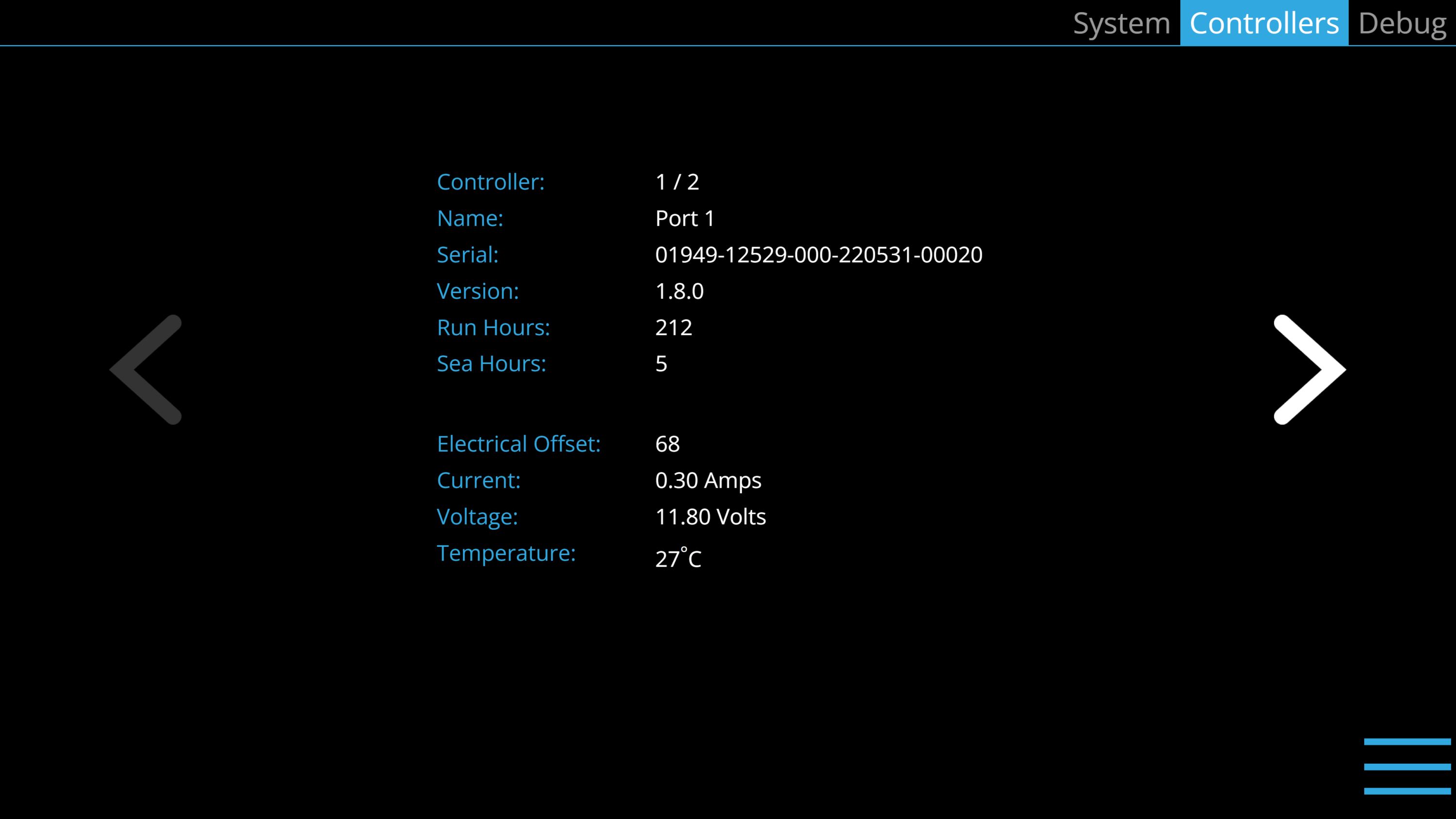
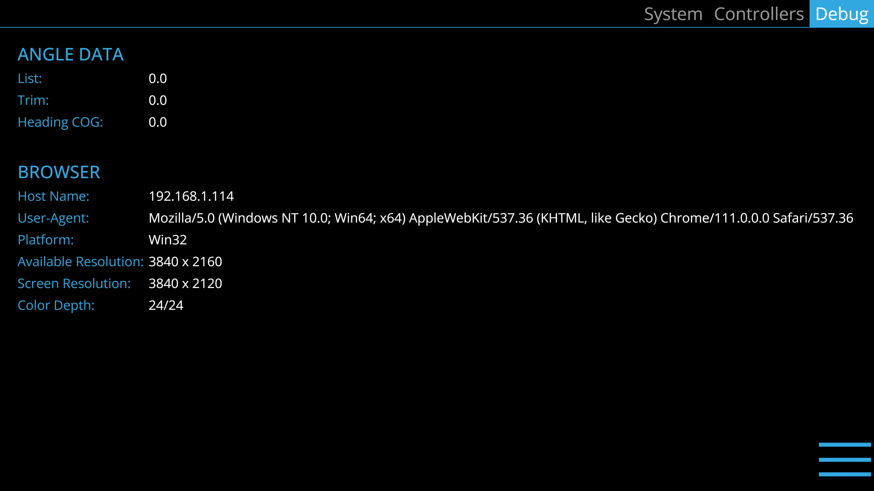
The Info page provides details about Seakeeper Ride components, serial numbers, software versions, and other information. The Info page below is an example and may not match information details of the installed Seakeeper Ride system. This information will be useful for warranty registration, software updates and troubleshooting.
Serial Numbers
When searching for serial numbers, the Software Module serial number is equivalent to the system serial number. To locate the Controller serial numbers, select the Controllers tab in the top right menu. Information on the port Controller will show, including serial number. Press the arrow on the right side of the page to switch to information on the starboard Controller.
Fault History
The Fault History page shows what faults and warnings that have occurred in the past and their associated run hours. The scroll bar on the right is used to move up and down through the list.
Seakeeper
If the boat is equipped with a Seakeeper gyroscopic stabilizer in addition to the Seakeeper Ride system, the Seakeeper icon in the navigation bar will allow the operator to switch between applications for each product. Both systems must be updated for this feature to be available.
3. Seakeeper Ride Operation
Seakeeper Ride Operation Introduction
Note: If the Seakeeper Ride system was not installed by the Original Equipment Manufacturer (OEM) (boat builder) or a professional Seakeeper certified installer, you must follow the Seakeeper Ride Commissioning Instructions to configure the equipment before operating the system.
3.1. Start Up
- Turn on the boat’s main power through the battery switch.
- Turn on the boat’s Multifunction Display (MFD) and GPS unit. Note: It may take several minutes to acquire satellites – a necessity for operation of Seakeeper Ride.
- Turn on engine key switch or Software Module Power. Note: The Controllers require approximately 30 seconds upon initial start up to sync with the other electronics. The Seakeeper Ride system will now automatically work to eliminate pitch and roll motions when travelling above 10 mph.
- Select the Seakeeper Ride application on the MFD to display and control the Seakeeper Ride system. ‘Auto’ will display in the Seakeeper icon button at the center of the digital keypad. On boats equipped with an optional Keypad, the Seakeeper icon in the center will illuminate to confirm the system is operating.
Note about Seakeeper Ride’s operation at different speeds:
- In Auto Mode, the Trim Command Curve adjusts the bow down influence of the system at speeds between 10 and 50 mph.
- In Auto Mode, the left and right directional arrows do not influence Seakeeper Ride movement below 10mph.
- In Manual Mode, the Controllers can be adjusted at any speed. The Controller Blades will retract when slowing down below 5 mph.
3.2. Shut Down
To power down Seakeeper Ride, turn off Software Module Power Switch or engine key switch depending on how your Seakeeper Ride system is installed. Seakeeper Ride system must be turned off while trailer or being transported to ensure no blade movement when the hull is not in the water.
3.3. Trim Command Curve (TCC)
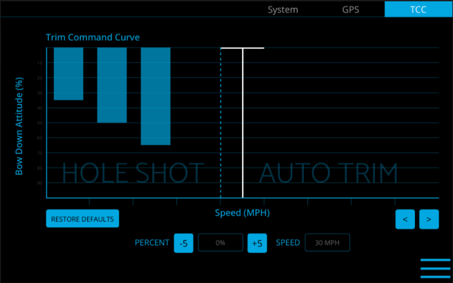
The Trim Command Curve (TCC) allows the operator to set a preferred trim at speeds of 10-50 mph in 5 mph increments. This important feature allows the boat to get on plane significantly faster by deploying the Blades when accelerating. The TCC additionally allows the operator to adjust the attitude of the bow by setting preferred Blade deployment at cruise speeds.
The TCC is split into two distinct zones, one for Hole Shot (from 10-25 mph) and one for Cruise (30-50 mph).
The Hole Shot from 10-25 mph is utilized strictly when the boat is accelerating, to bring the bow down and maintain a view of the horizon. This feature does not function when decelerating, preventing stuffing the bow of the boat. To re-engage, the boat must slow below 5 mph before accelerating again.
The Cruise portion of the Trim Command Curve is active from 30-50 mph providing additional bow down attitude as preset by the operator if the boat is accelerating, maintaining speed, or slowing down. Only customize the Trim Command Curve in this speed range after attempting to trim the boat using the motor trim and distributing the weight of passengers and other loads evenly on the boat.
Notes on the TCC:

Note: The trim of boats with adjustable propulsion like outboard motors, stern drives and surface drives is largely dependent on the trim of the propulsor. Please familiarize yourself with proper operation of the propulsion trim before adjusting the TCC. For boats with 3 or more engines, where Seakeeper Ride is mounted forward of the propellers, we recommend reducing TCC to 0 for all speeds and then working to increase TCC as desired.
The TCC will be preset. To customize the TCC:
- Follow the steps to turn on the system in Section 3.1.
- Ensure the boat is in neutral in safe waters with no obstructions or boat traffic.
- With the Seakeeper Ride system turned on, select the Menu button
 on the MFD.
 - Select the Settings button
 from the menu.
 - Select the TCC button in the upper right corner of the screen.
- The display shows speed at the bottom (x-axis) and percent on the dependent axis (y-axis).
- Use the right and left arrows
 to select a speed segment. Each speed segment is 5 mph. Speed segments start at 10mph and go to 50mph. The advanced software will smoothly transition through each speed trim for seamless operation.
 - By selecting the percent buttons on the bottom, add or subtract the trim command at that given speed segment.

The trim command is shown as blue fill in each column. More trim command results in more bow down influence on the boat by the Controllers. Less trim command results in less bow down influence on the boat.
- Perform a test of the selected settings by maneuvering the boat into calm open water. Once clear, accelerate the boat through the full range of speeds and monitor how the trim of the boat behaves at each speed.
- Further adjustments can be made by repeating steps 1 through 9.
3.4. Operation Notes
Blade Deployment
As with any boat, when operating a boat with Seakeeper Ride, distribute onboard weight evenly and make any other adjustments that allow the boat to run comfortably and efficiently. Doing this will minimize the need for Seakeeper Ride to deploy the Blades as deeply and as frequently to compensate for static variables and will maximize overall performance. Bear in mind that operator bias including Trim Command Curve, irregularities in loading, wind conditions, asymmetrical hull shapes, or any other factor that may cause a boat to list will cause Seakeeper Ride to deploy the Blades deeper and more frequently and could produce more aeration downstream. Operators should be aware of this in applications where the Ride Blades are located forward of propellers and there is overlap as described in Installation Location 450, 525, 600 or Installation Location 750