Maintenance Schedule
Maintenance
Maintenance Introduction
Updated 10/16/25
A regular inspection and cleaning of the Seakeeper Ride system is recommended. Zinc sacrificial anodes should be monitored and replaced as needed or according to the schedule below. Bottom paint should be applied in applications where the Controllers will be submerged for more than two (2) weeks at a time. Refer to the following sections for details on cleaning, removing broken or exhausted parts, and reinstalling components on the Seakeeper Ride system.
Follow the table below for recommended scheduled maintenance.
| System / Component | Task | Interval | Parts / Special Tools |
| Mechanical / Corrosion | Inspect/replace sacrificial anode. 2. Zinc Sacrificial Anode Replacement – Seakeeper Manuals | 6 Months or 500 Hours | Sacrificial Anode Part Number: Zinc-12833SP Aluminum-12909SP 750-1500 Anodes (Per controller)-13771 |
| Mechanical / Fasteners | Check Seal Plate bolts are still at torque spec for 450, 525, 600 or 750-1500 | 3 Months or 250 Hours | Torque wrench |
| Actuator Friction | Check Actuator is held tightly in place by Seal Plate. Seakeeper Ride | Check Actuator Friction – Seakeeper Manuals | 3 Months or 250 Hours | |
| Electrical / Connectors | Inspect all connectors for corrosion, replace if necessary. | 12 Months or 1000 Hours | |
| Electrical / Grounds | Inspect all ground points for corrosion, clean as necessary, and treat with corrosion inhibitor. | 12 Months or 1000 Hours | |
| Electrical / Cables | Check all cables and wire harness branches for cracks or chafing. | 12 Months or 1000 Hours |
Note: Recommended scheduled maintenance is not covered under warranty.
Note: 1 order of 750-1500 anodes (Part number 13771) are per Controller.
1. Cleaning Seakeeper Ride
It is recommended to clean the Seakeeper Ride Controllers often, along with the rest of the boat. The Controllers can be cleaned with all the components left in place. Cleaning should be done every time the boat is removed from the water through the following steps:
- Spray the Controllers and boat down with fresh, clean water using a hose or power washer. When power washing, to avoid damaging the Controllers:
- Do not use less than a 15 degree nozzle. Do not use a rotating or turbo nozzle.
- Spray at least 18 inches away from the Controllers.
- Maintain continuous movement.
- Apply a mild marine soap.
- Scrub with a scrub brush or rag to remove salt residue, grime, etc.
- Remove additional grime and residue with a hose or power washer on low power.
- Rinse with fresh, clean water.
If the boat is kept in the water, maintain a monthly check of marine growth on the equipment. Regularly brushing growth off is best practice. Reviewing sacrificial anodes for growth or crusting (passivation) should coincide with the check for marine growth on the rest of the equipment. Use a scotch bright pad or soft copper brush to lightly clean the zincs between splashes.
If the boat is kept out of the water, the zinc sacrificial anodes must be brushed clean between usage to allow the surface to remain active and avoid crusting (passivation). Use a scotch bright pad or soft copper brush to lightly clean the zincs between splashes.
When using a pressure washer to clean the Controllers, be careful around seals and cable glands to avoid damage. The Blade may occasionally be removed to clean underneath. If this is done, take great care to not damage the inside face of the Blade or trailing edge of the Seal Plate. The gap between these surfaces is precise and must remain at factory fitment. When reinstalling the Blade use thread locking sealant and activator/primer on the bolts and use a torque wrench to tighten bolts to the correct specification.
2.1 Sacrificial Anode Replacement 450, 525, 600
The Actuators on each controller have zincs that need to be periodically inspected and replaced when about half of the anode has worn down. Zincs can be purchased through Seakeeper. To replace the zinc sacrificial anodes:
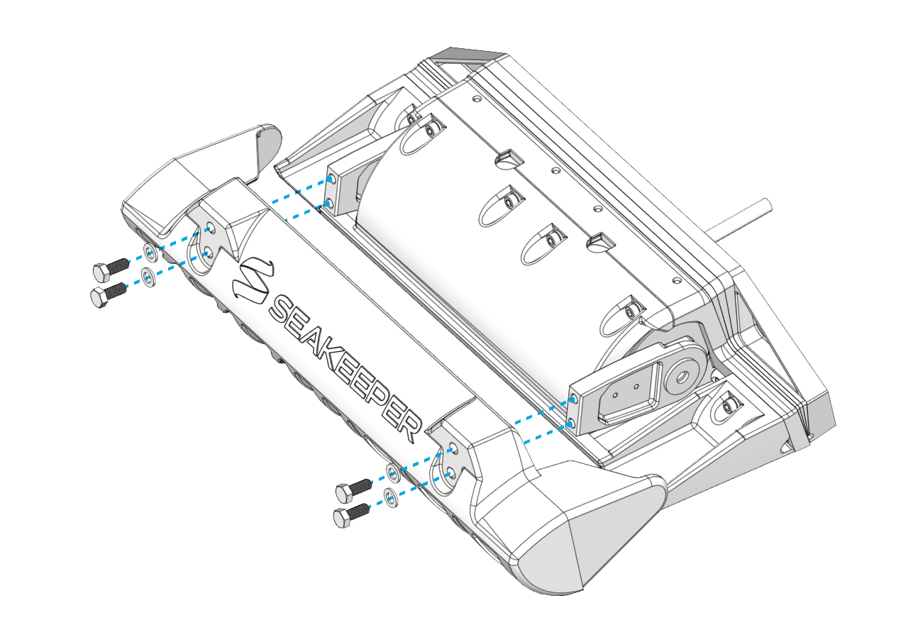
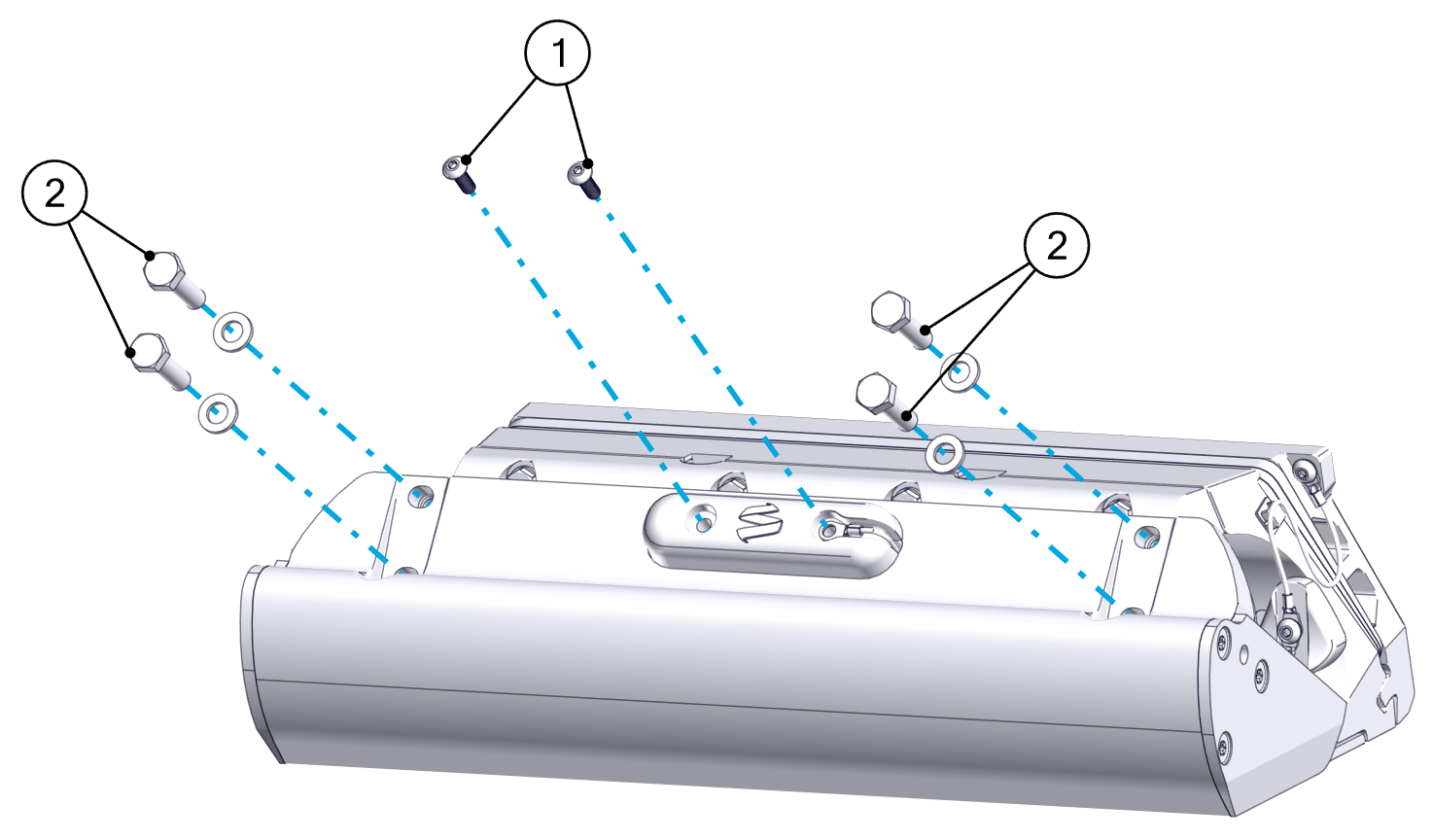
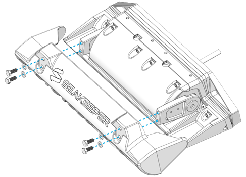
- Remove the Blade by unscrewing the four (4) M8-1.25 x 20 mm screws and their washers.
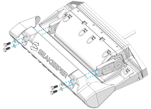
- Unscrew the two (2) M4-0.7 x 12 mm bolts holding the Zinc Sacrificial Anode.
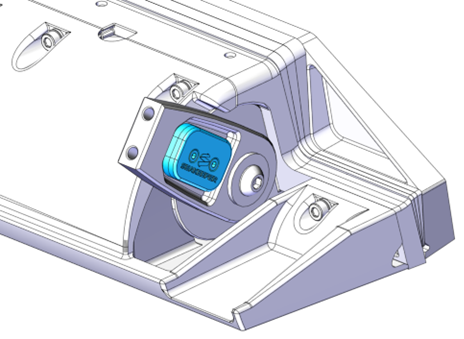
- Attach the new zinc sacrificial anode using the two (2) M4-0.7 x 12 mm bolts and tighten to 20 in-lbs (2.3 N-m).
- Reattach the Blade using the four (4) M8-1.25 x 20 mm screws and their washers. Be sure to use thread locking sealant with an activator/primer when reinstalling hardware. Torque these four (4) bolts to 80 in-lbs (9.0 N-m) in an “X” pattern.
2.2 Sacrificial Anode Replacement 750-1500
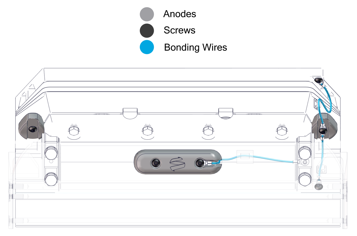
Sacrificial anodes on Seakeeper Ride should be inspected regularly, at least every 6 months or 500 hours. When the anodes are significantly worn, they must be replaced following the steps below.
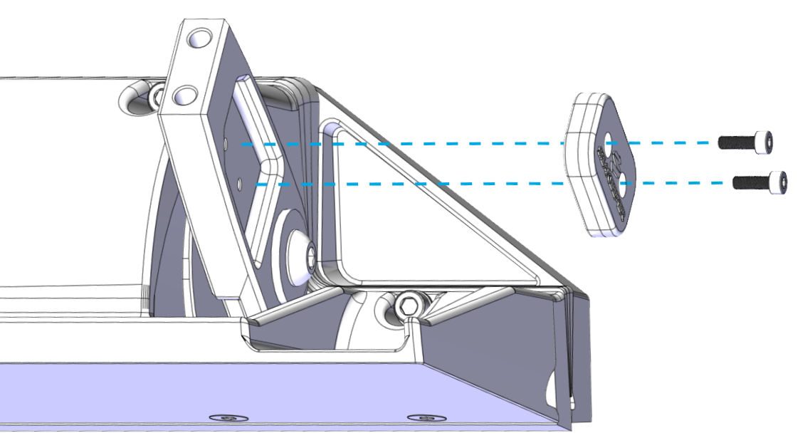
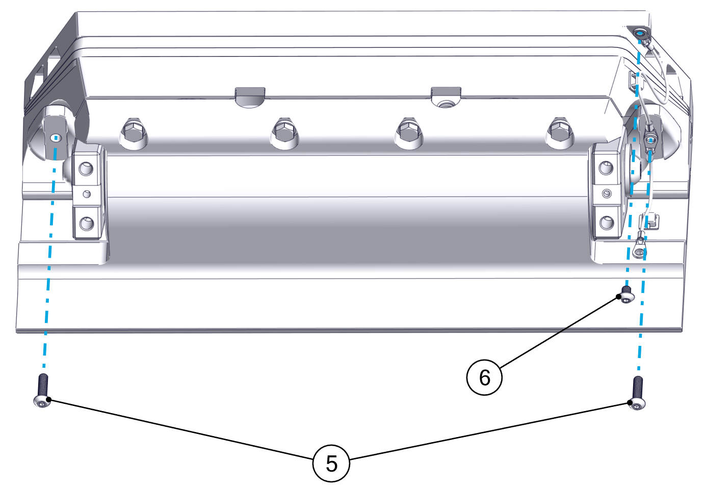
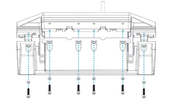
- Unscrew the two front M5 screws to remove the Blade anode.
- Unscrew the four M8 Blade bolts and carefully set the Blade aside. The bonding wire attached to the Blade will need to be fed through the hole in the center and detached from the clip on the inside.
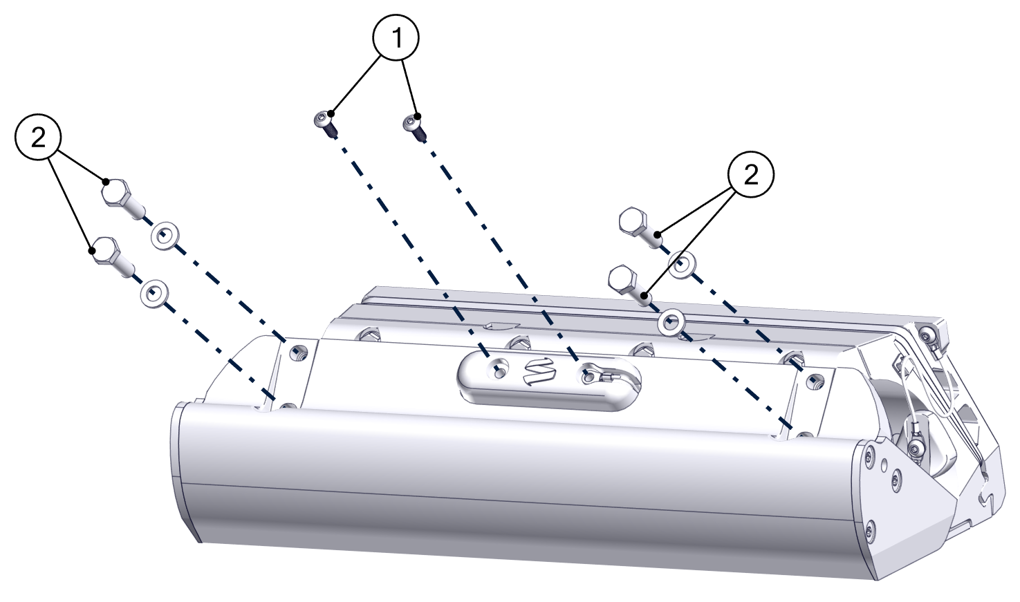
- Unscrew the M5 screw from the Blade Arm to remove the front bonding wire.
- Unscrew the M5 screw from the Seal Plate.
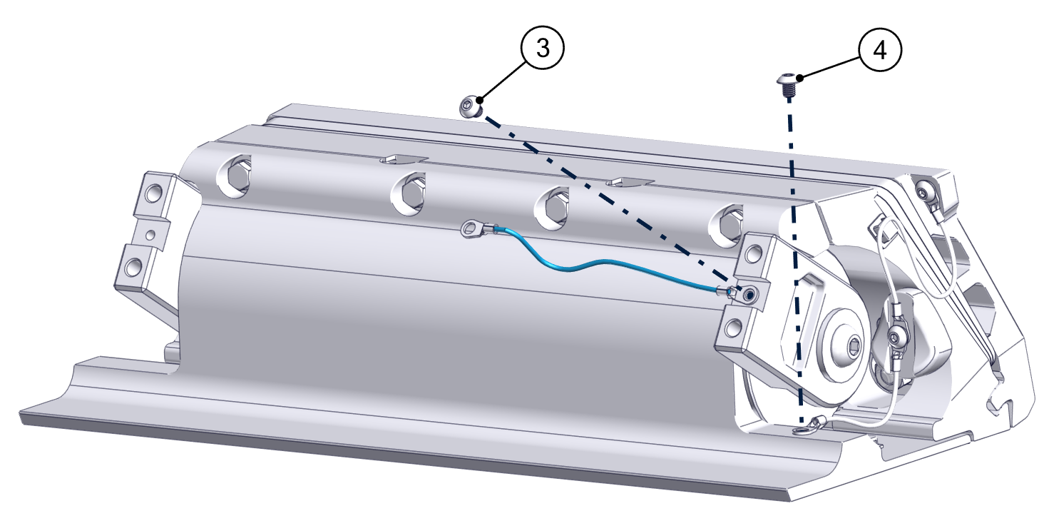
- Unscrew the two M5 screws from the Actuator Plate to remove the anodes. This will also free the bonding wire from the Seal Plate to the Actuator Plate.
- Unscrew the M5 screw from the top right of the Transom Plate to remove the final bonding wire.
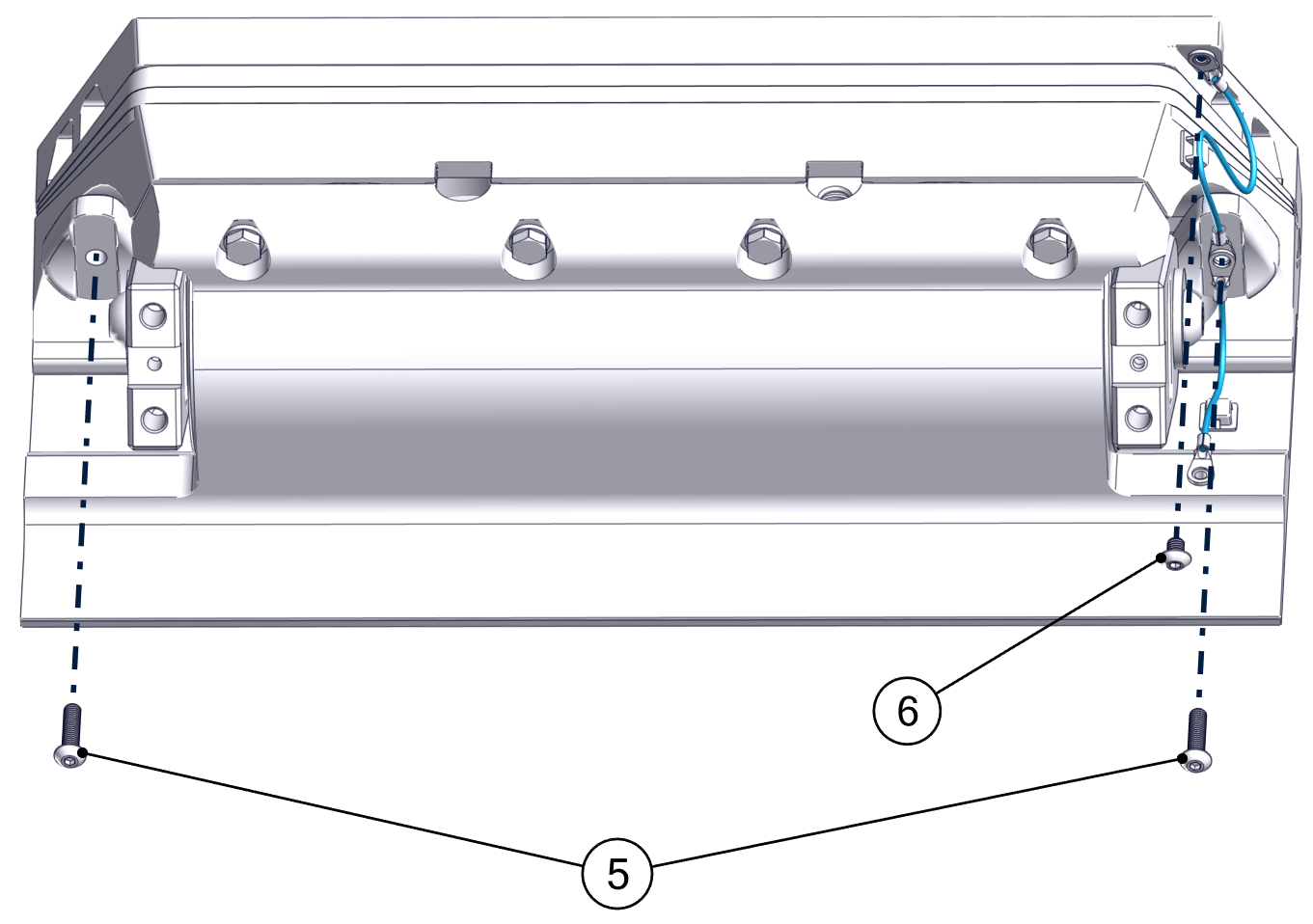
- Replace all bonding wires, anodes, and the Blade by reversing the steps above. Apply Vibra-Tite VC3 threadlocker to all fasteners before reinserting. Torque all M5 screws to 25 in-lbs (2.8 N-m). Torque the four M8 Blade bolts to 130 in-lbs (14.7 N-m).
3.1 Bottom Painting 450, 525, 600
To prevent marine growth and increase longevity of the components, the Seakeeper Ride Controllers may be coated in antifouling paint, also known as bottom painting. This is recommended if the boat will be in the water for more than two (2) weeks at a time. Follow the instructions in this document to ensure the best results when bottom painting Seakeeper Ride.
Choose a bottom paint that best fits the usage and storage of the boat. Avoid paints that contain metals for biocide, as it may cause corrosion damage to the stainless steel and aluminum components. Spray on paints are easier than roll on but may take more time in preparation to prevent overspray on undesired surfaces.
Ride 450, 525 and 600 Controllers
To bottom paint Seakeeper Ride Controllers:
- Remove the Blade by unscrewing the four (4) M8-1.25 screws and their washers.
- Use masking tape to cover surfaces that will not be painted. This includes the inside of the Blade, trailing edge of the Seal Plate, stainless steel hardware and arms, and any part of the boat that will be left unpainted. Controller components that should be protected with tape are shown in blue in the figure below.
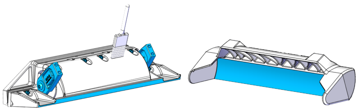
- Follow the instructions and recommendations associated with the paint being used for surface preparation on the SMC parts (Seal Plate, Blade, Actuator Plate, Wedge Plates, and Transom Plate) supplied. The SMC parts are similar to fiberglass in that they are a fiber reinforced plastic. As such, the surface can be sanded and wiped with solvents like acetone to prepare them for paint adhesion. Be careful not to gouge, cut, or sand deeply into the SMC parts. Removing too much material will reveal the reinforcing fibers and could reduce their structural strength.
Do not sand or scuff the stainless steel torque arm or aluminum body of the Actuator. Do not scuff or alter the inside of the Blade or trailing edge of the Seal Plate. The gap between these surfaces is precise and must remain at factory fitment. Surfaces that must not be scuffed are shown in blue in the figure above.
- Apply the selected bottom paint to the Blade and the rest of the Controller assembly. Do not paint the inside of the Blade and trailing edge of the Seal Plate. Adding paint to these surfaces will cause the parts to contact during operation and greatly reduce system performance. Avoid painting the stainless steel hardware and arms. Surfaces that must be left unpainted are shown in blue in the figure above. Paint all other accessible surfaces.
- Reattach the Blade using the four (4) M8-1.25 x 20 mm screws and their washers. Be sure to use approved thread locker when reinstalling hardware. Torque these four (4) bolts to 80 in-lbs (9.0 N-m) in an “X” pattern.
3.2 Bottom Painting 750-1500
To prevent marine growth and increase longevity of the components, the Seakeeper Ride Controllers may be coated in antifouling paint, also known as bottom painting. This is recommended if the boat will be in the water for more than two (2) weeks at a time. Follow the instructions in this document to ensure the best results when bottom painting Seakeeper Ride.
Choose a bottom paint that best fits the usage and storage of the boat. Avoid paints that contain metals for biocide, as it may cause corrosion damage to the stainless steel and aluminum components. Spray on paints are easier than roll on but may take more time in preparation to prevent overspray on undesired surfaces.
To bottom paint Seakeeper Ride Controllers:
- Remove the front Blade anode by unscrewing the two (2) M5-0.8 screws.
- Remove the Blade by unscrewing the four (4) M8-1.25 screws and their washers.
- Remove the Actuator Arm bonding wire by unscrewing the M5-0.8 screw.
- Remove the M5-0.8 screw securing the bonding wire to the Seal Plate.

- Remove the two (2) Actuator Plate anodes by removing the M5-0.8 screws securing them. This will also free the bonding wire from the Actuator Plate to the Seal Plate.
- Remove the M5-0.8 screw securing the bonding wire to the Transom Plate to release the final bonding wire.
- Use masking tape to cover surfaces that will not be painted. This includes the inside of the Blade, trailing edge of the Seal Plate, stainless steel hardware and arms, and any part of the boat that will be left unpainted. Controller components that should be protected with tape are shown in blue in the figure below.
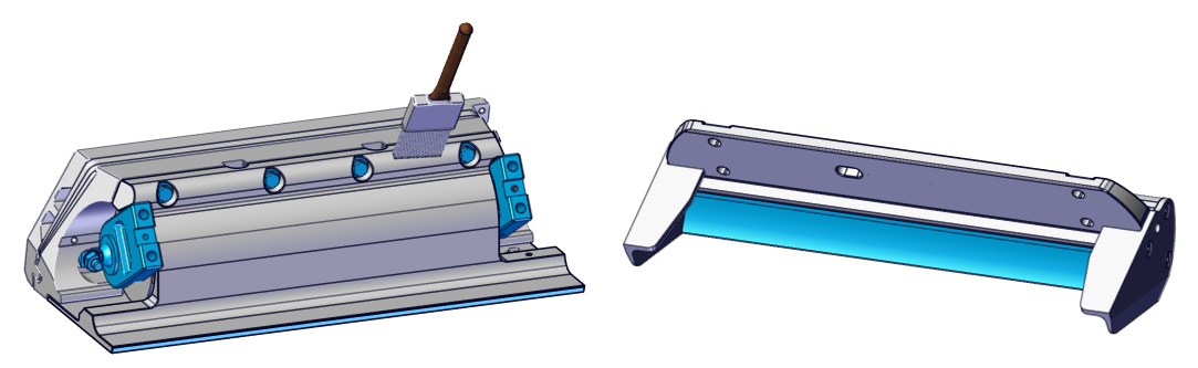
- Follow the instructions and recommendations associated with the paint being used for surface preparation on the coated aluminum parts (Seal Plate, Blade, Actuator Plate, Wedge Plates, and Transom Plate) supplied. The surface can be abraded using a scouring pad and wiped with alcohol to prepare them for paint adhesion. Be careful not to gouge, cut, or sand deeply into the coated parts. Removing the coating completely will expose the aluminum to water and corrosion.
Do not sand or scuff the stainless steel torque arm or aluminum body of the Actuator. Do not scuff or alter the inside of the Blade or trailing edge of the Seal Plate. The gap between these surfaces is precise and must remain at factory fitment. Surfaces that must not be scuffed are shown in blue in the figure above.
- Apply the selected bottom paint to the Blade and the rest of the Controller assembly. Do not paint the inside of the Blade and trailing edge of the Seal Plate. Adding paint to these surfaces will cause the parts to contact during operation and greatly reduce system performance. Avoid painting the stainless steel hardware and arms. Surfaces that must be left unpainted are shown in blue in the figure above. Paint all other accessible surfaces.
- Reattach the anodes, bonding wires and Blade by reversing the steps above. Be sure to use approved thread locker when reinstalling hardware. Torque these four (4) Blade bolts to 130 in-lbs (14.7 N-m) in an “X” pattern.
4. Blade and Seal Plate Removal
If a Blade or Seal Plate is broken or needs to be removed for any other reason, refer to the steps below. Note that the various Ride controllers have different quantities of hardware depending on the specific model.
- Remove the Blade by unscrewing the four (4) M8-1.25 x 20 mm screws and their washers.
- With the Blade removed, begin removing the Seal Plate by unscrewing the M6-1.0 x 16 mm Allen head screws on the underside of the Seal Plate.
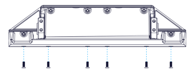
- Finish removing the Seal Plate by unscrewing the M6-1.0 x 30 mm bolts and washers on the front of the Seal Plate.
5. Software Module Replacement
If the Software Module is damaged or needs to be replaced for any other reason, refer to the following steps:
- Turn off power to the boat.
- Use tape and a writing utensil or some other method to label the three (3) cables connected to the Software Module: NMEA, SK, and Ethernet.
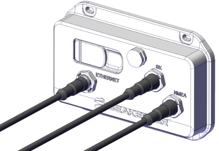
- Disconnect the three (3) cables from the Software Module.
- Remove the four (4) No. 10 x 1 in. mounting screws.
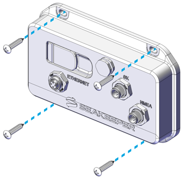
- Remove the old Software Module and hold the new Software Module in place.
- Reinsert and tighten the four (4) No. 10 x 1 in. mounting screws.
- Reattach the three (3) cables to the Software Module according to the labels.
- Power the boat back on, and follow the instructions to calibrate the new Software Module in the Seakeeper Ride Configuration Instructions.
6. Reinstalling Components
When reinstalling any component of Seakeeper Ride during maintenance, make sure to reapply thread locking sealant activator/primer and thread locking sealant to bolts. Use a torque wrench to tighten bolts to the correct specification linked below. Bolts or screws not listed below do not have a torque specification and should be tightened snug to prevent movement but not overtightened. Do not tighten bolts in a straight or circular path, one right after another. Instead, tighten in an alternating or ‘X’ pattern.