Seakeeper 1 Installation Manual (90519-2) 1-233-0631 to Current
Electrical Installation
Electrical Installation Introduction
This section for electrical installation explains how to mount the electrical equipment and how to connect the electrical cables.
Reference Documents & Drawings:
- 90510 – Seakeeper 1 Hardware Scope of Supply
- 90511 – Seakeeper 1 Cable Block Diagram
- 90512 – Seakeeper 1 Cooling Water Schematic
- Seakeeper Multifunction Display Compatibility Bulletins:
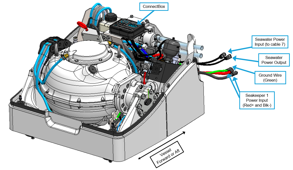
Figure 1 – Seakeeper 1 Isometric View with Electrical Connections
he following images show the electrical equipment included with the Seakeeper 1 Hardware Scope of Supply (Drawing No. 90510):
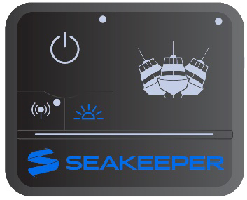
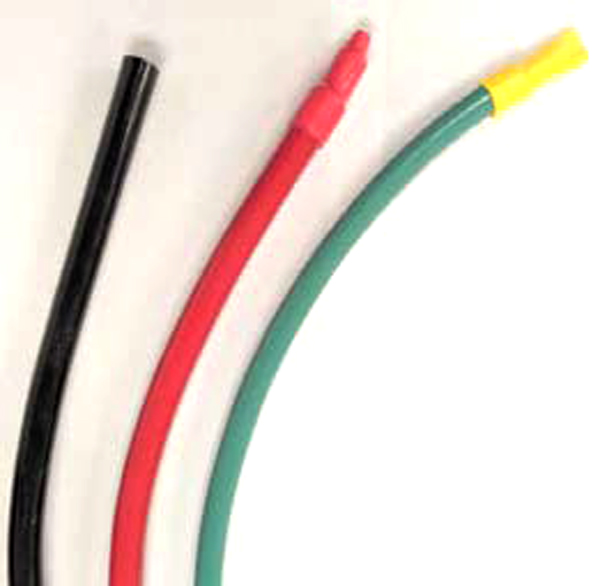
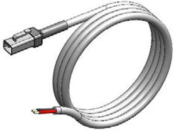
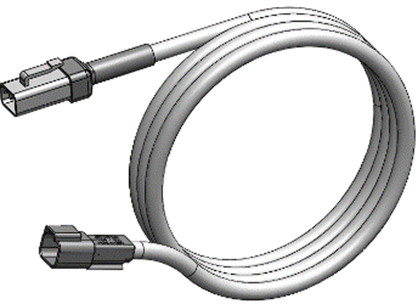
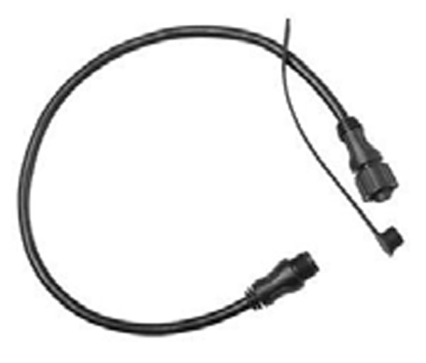
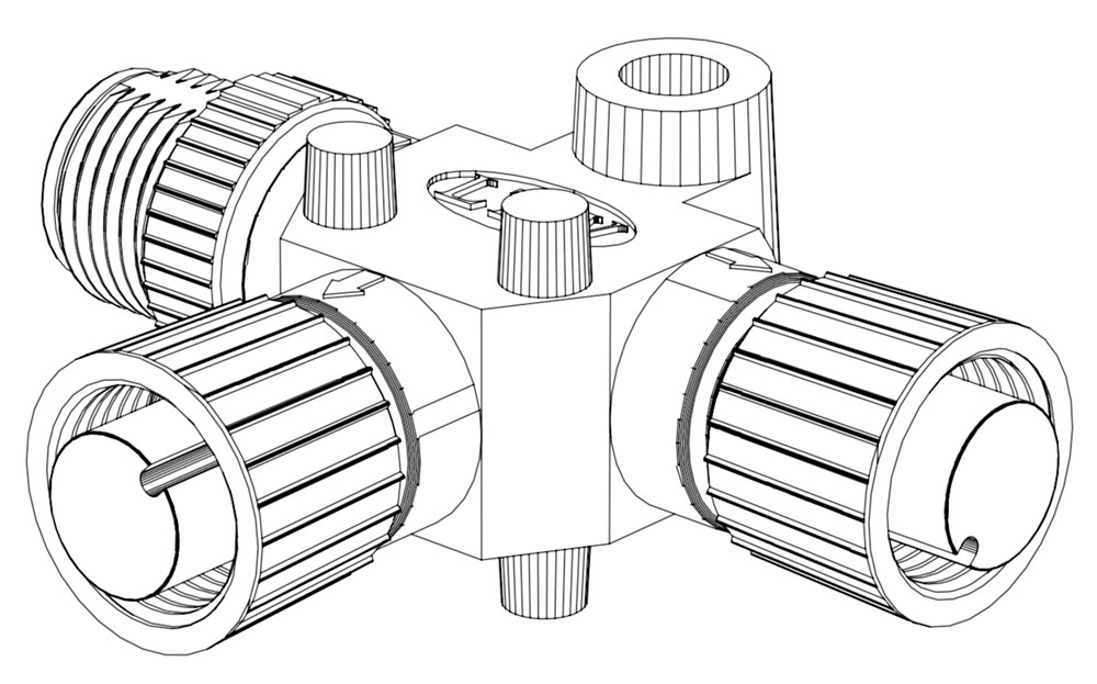
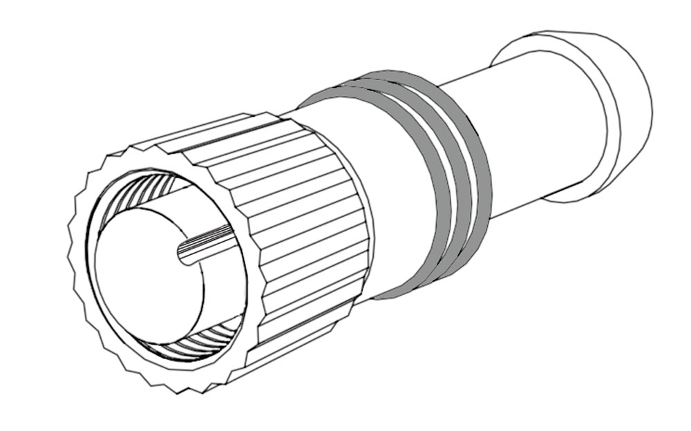
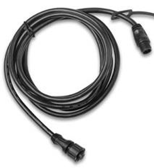
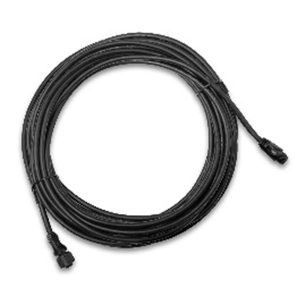
Figure 2 – Electrical Equipment for Seakeeper 1
Electrical Equipment Connections
High Current 12 VDC Power Source Requirements:
| Source | Battery Bank, 12 VDC, Marine, Deep Cycle |
| Voltage Range | 11.3 – 16 VDC |
| Continuous Current | 55 A |
| Overcurrent Protection | 80 A (Customer Supplied) |
High Current 12 VDC Power Connection Instructions
- Connect Cable 1 and Cable 2, 2 AWG conductors, to the 12 VDC power source.
- Cable 1 and Cable 2 are supplied as length 0.35 m and approximately 0.1 m is routed within the gyro frame.
- Splice customer-supplied 2 AWG conductors to Cable 1 and Cable 2 in accordance with the Crimping Instructions in Drawing No. 90511 – Seakeeper 1 Cable Block Diagram, using Seakeeper-supplied butt connectors, to increase conductors to desired length. The maximum cable length is 29.53 ft (9.0 m) each.
- Crimp Cable 1 to B+ Conductor (red). Conductor should be continuous throughout entire length; do not coil. The most direct route to the 12 VDC power source should be used.
- Repeat Step 3 for Cable 2 to B- Conductor (black).
- Install approximately 2 in. (51 mm) of double wall (adhesive lined) heat shrink tubing over entire butt connector and onto both sides of conductor insulation.
- Connect plus conductor (B+, red) through dedicated 80 A overcurrent protection device (customer-supplied) and a dedicated isolation switch (customer-supplied), then directly to battery plus terminal or bus bar.
- Connect minus conductor (B-, black) directly to battery minus terminal or DC negative bus.
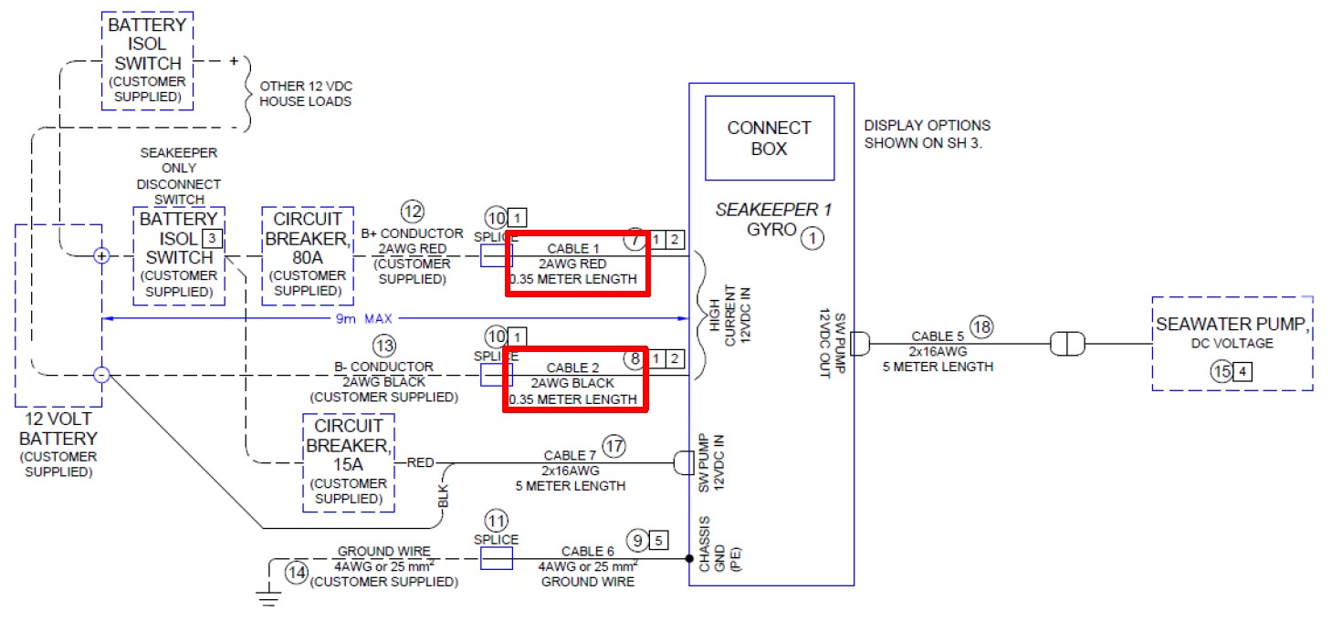
Figure 3 – Seakeeper 1 Cable Block Diagram (Drawing No. 90511) – High Current Connection

Reversing polarity on the DC power input to the Seakeeper can result in damaging the electronics in the control system.
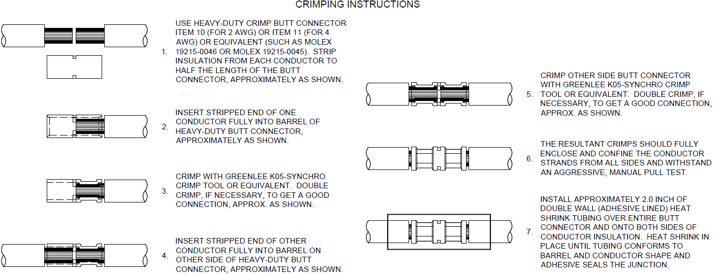
Figure 4 – High Current DC Input Crimping Instructions (Drawing No. 90511)
Seawater Pump 12 VDC Power Source Requirements
| Power Source | Battery Bank, 12 VDC, Marine, Deep Cycle |
| Voltage Range | 10 – 16 VDC |
| Current Rating | Max 15 A rating |
| Overcurrent Protection | Per pump specification, max 15 A |
Seawater Pump 12 VDC Power Input Connection Instructions
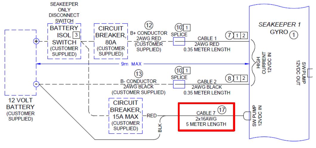
- Connect Cable 7 (P/N: 30327) to Seakeeper 1 “SW Pump DC In” as shown in Drawing No. 90511 – Seakeeper 1 Cable Block Diagram, with overcurrent protection corresponding to seawater pump selected.
- Connect the 14 AWG plus conductor (red) through dedicated overcurrent protection device (customer-supplied), maximum of 15 A, to dedicated battery isolation switch.
- The Cable 1, 2 AWG B+ conductor (red), is capable of carrying the current for both the High Current and Seawater Pump from the 12 VDC power supply to the battery isolation switch.
- Connect the 14 AWG minus conductor (black) directly to battery minus terminal or DC main negative bus.
Seawater Pump 12 VDC Power Output Connection Instructions
- Connect Cable 5 to the Seakeeper 1 “SW Pump 12 VDC Out” for DC power output to the seawater pump. Cable 5 is a 2 x 16 AWG cable, 16 ft (5 m) length, with a size 16 female Deutsch plug.
- Pumps rated at 12 VDC, 15 A maximum, customer-supplied, must be configured with a Deutsch DT series, 2-pin receptacle to mate with the connector shown in the following figure.
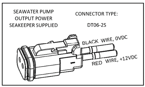
- Cable 5 must be routed and installed in the vessel from the Seakeeper 1 “SW Pump 12 VDC Out” Deutsch connector (pins end) to the DC seawater pump cable Deutsch connector (socket end).
- Connect Cable 5 plug end (socket end) to the customer-supplied receptacle end (pins end). The recommended wiring is shown in the following figure.
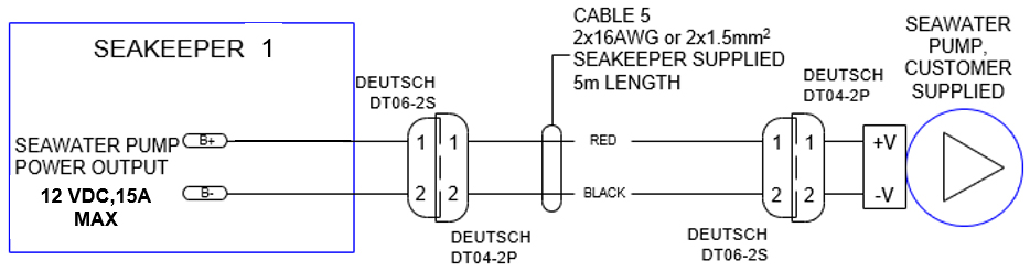
Figure 7 – Cable 5 – Seawater Pump
- Seakeeper DC Seawater Pump Assembly (P/N 30331), which is prewired for Cable 5, is available as an option with the Seakeeper 1.
Electrical Equipment Ground Connections
Seakeeper 1 to Vessel Ground Connection Instructions
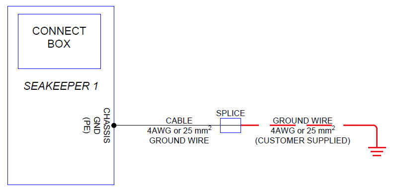
- Connect Ground Cable, 4 AWG (25 mm2), PE cable to vessel grounding bus to comply with:
- EM/IEC 60204-1: 2016 Clauses 6.3.3 and 8.2.3.
- ABYC E-11 July 2021Clauses 11.5.2 and 11.17.
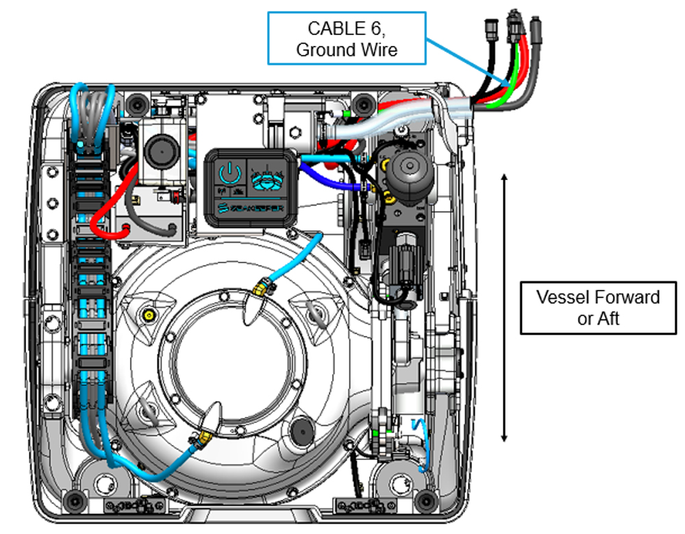
- Butt splice Ground Cable from Seakeeper, 4 AWG (green) to a 4 AWG (25 mm2) ground wire (customer-supplied) suitable in length for the specific installation, as shown in the following figure.
- Note: GROUND CABLE (GREEN) SHOULD ONLY BE USED FOR GROUNDING THE SEAKEEPER TO THE VESSEL GROUND.
Seakeeper 1 Display Connection
Seakeeper 1 Display Options
The Seakeeper 1 requires a compatible Multifunction Display (MFD).
A display is required with the installation of a Seakeeper 1 to support the full functionality ofthe unit through the
Seakeeper App in addition to the ConnectBox. The Seakeeper Appprovides an interface for controlling the Seakeeper 1 or viewing the Settings, Service, Info,and Alarm pages. The Seakeeper ConnectBox can be helm-mounted to provide an additionalinterface for controlling the Seakeeper 1 but does not replace the need for a
Seakeeper -compatible display.
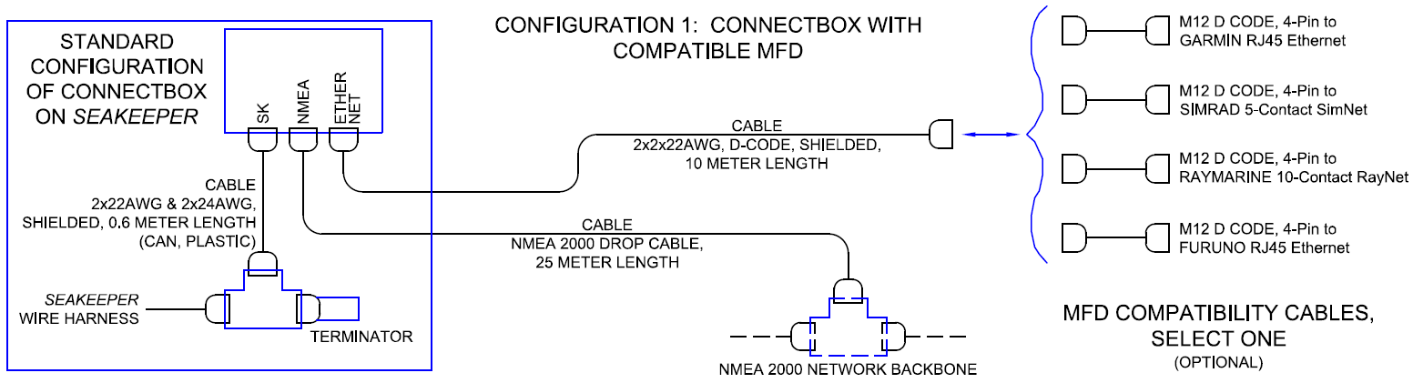
Figure 10 provides a schematic of the display installation:
Connecting to an Optional Compatible MDF
- The Seakeeper 1 can be connected to a variety of available MFD systems. Refer to the Technical Bulletins Section of the Seakeeper Technical Library for manufacturer specific MFD compatibility technical bulletins.
- MFD specific Technical Bulletins will be updated regularly as new MFD systems become compatible. Currently GARMIN, RAYMARINE, SIMRAD, and FURUNO offer compatible MFD models.
- Once a compatible MFD has been selected, refer to the appropriate manufacturer specific Technical Bulletin for integration instructions.
- Connect Seakeeper-supplied Cable 10, D-Code 10 m cable to MFD manufacturer-specific Ethernet adapter cable. Custom Ethernet cables for specific MFD manufacturers are available through Seakeeper and must be purchased with the Seakeeper 1 if connecting to an MFD.
NMEA 2000 Network Connection
The Seakeeper 1 requires a connection to the vessel’s NMEA 2000 network backbone. The Seakeeper 1 will monitor information on the NMEA network to support and optimize the performance of the Seakeeper 1.
- Connect Seakeeper-supplied Cable 11 to the customer-supplied NMEA 2000 Tee Adapter on vessel’s NMEA 2000 backbone.
- An active NMEA 2000 compatible GPS signal is required on the vessel’s NMEA 2000 backbone to operate the Seakeeper 1.
- If no GPS signal is detected, a warning will be present on the Seakeeper App.
- An active NMEA 2000 compatible GPS signal is required on the vessel’s NMEA 2000 backbone to operate the Seakeeper 1.
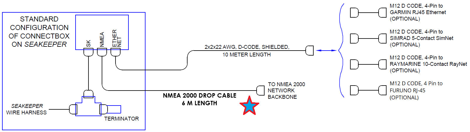
ConnectBox Helm Mounting – Optional
- Remote ConnectBox mounting requires Seakeeper part number 90558, ConnectBox Remote Mount Kit.
- Console space required: Approx. 3.41 L x 4.15 W in. (87 x 106 mm).
- Mounting Instructions, Surface Mount: See Drawing No. 90558 – Seakeeper 1 ConnectBox Helm Mounting Kit, for details. Seakeeper ConnectBox 3D Model available upon request.
- Mount ConnectBox Replacement Blank Insert (P/N 12206) into Seakeeper 1 enclosure at the original location of the ConnectBox.