Seakeeper 1 Installation Manual (90519-2) 1-233-0631 to Current
Connecting Seawater to Heat Exchanger
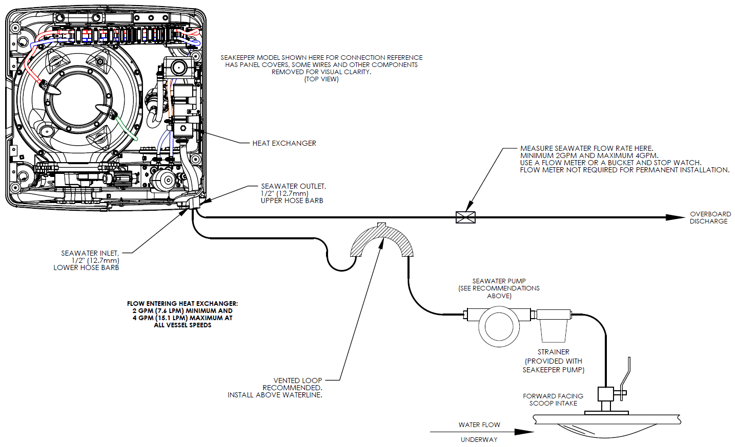
Refer to Figure 2 for typical seawater plumbing arrangement.
- Connect seawater pump to Seakeeper dedicated through-hull fitting. A strainer and seacock valve should generally be installed between the seawater inlet and the pump.
- Connect seawater from installer-supplied seawater pump to lower ½ in. (13 mm) hose barb on heat exchanger.
- Use the same practices as other below waterline seawater plumbing.
- Connect seawater discharge (upper hose barb) to overboard drain. Use the same practices as other below waterline seawater plumbing.
- During commissioning, seawater flow should be checked to be within the flow requirements while the vessel is at rest, at speed, and when backing down.
- If no other method of confirming flow is available, discharge line may be temporarily diverted to a bucket. Flowrate is calculated based on the time required to fill a known volume in GPM / LPM.
- Flowrates in excess of 4 GPM (15.2 LPM) could affect heat exchanger life.
- After sea trial/commissioning, inspect all raw water plumbing for any signs of leakage.
Seakeeper Optional DC Seawater Pump (P/N 30331)
| Volts | 24 VDC (operate at 12 V for Seakeeper 1) |
| Rated Flow | 2.5 GPM (9.5 LPM), at 12 VDC |
| Overcurrent Protection Rating | 15 A |
| Ignition Protection | ISO 8846 or equivalent |
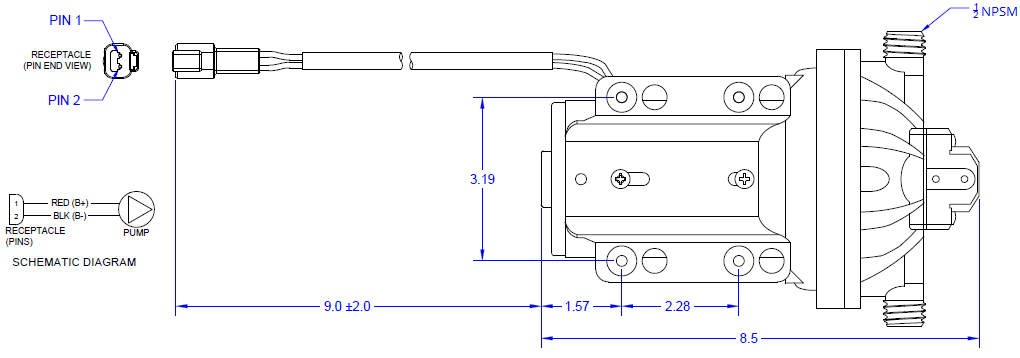
- Seakeeper offers a self-priming DC Seawater pump as an optional addition. DC Seawater Pump, Seakeeper 1 Assembly (P/N 30331), is shown in the following figure.
- The Seakeeper Seawater Pump is a 24 VDC pump operated at 12 VDC for the Seakeeper 1 and maintains a seawater flow of approximately 2.5 GPM (9.5 LPM) at 12 VDC.
- The pump assembly is pre-wired for connection to Seakeeper 1 Seawater Pump Output Cable and includes a seawater strainer and various fittings.
NOTE: Use only SeaFlo®-provided threaded fittings for DC Seawater Pump 30331.