Seakeeper 1 Installation Manual (90519-2) 1-233-0631 to Current
Electrical Equipment Connections
High Current 12 VDC Power Source Requirements:
| Source | Battery Bank, 12 VDC, Marine, Deep Cycle |
| Voltage Range | 11.3 – 16 VDC |
| Continuous Current | 55 A |
| Overcurrent Protection | 80 A (Customer Supplied) |
High Current 12 VDC Power Connection Instructions
- Connect Cable 1 and Cable 2, 2 AWG conductors, to the 12 VDC power source.
- Cable 1 and Cable 2 are supplied as length 0.35 m and approximately 0.1 m is routed within the gyro frame.
- Splice customer-supplied 2 AWG conductors to Cable 1 and Cable 2 in accordance with the Crimping Instructions in Drawing No. 90511 – Seakeeper 1 Cable Block Diagram, using Seakeeper-supplied butt connectors, to increase conductors to desired length. The maximum cable length is 29.53 ft (9.0 m) each.
- Crimp Cable 1 to B+ Conductor (red). Conductor should be continuous throughout entire length; do not coil. The most direct route to the 12 VDC power source should be used.
- Repeat Step 3 for Cable 2 to B- Conductor (black).
- Install approximately 2 in. (51 mm) of double wall (adhesive lined) heat shrink tubing over entire butt connector and onto both sides of conductor insulation.
- Connect plus conductor (B+, red) through dedicated 80 A overcurrent protection device (customer-supplied) and a dedicated isolation switch (customer-supplied), then directly to battery plus terminal or bus bar.
- Connect minus conductor (B-, black) directly to battery minus terminal or DC negative bus.
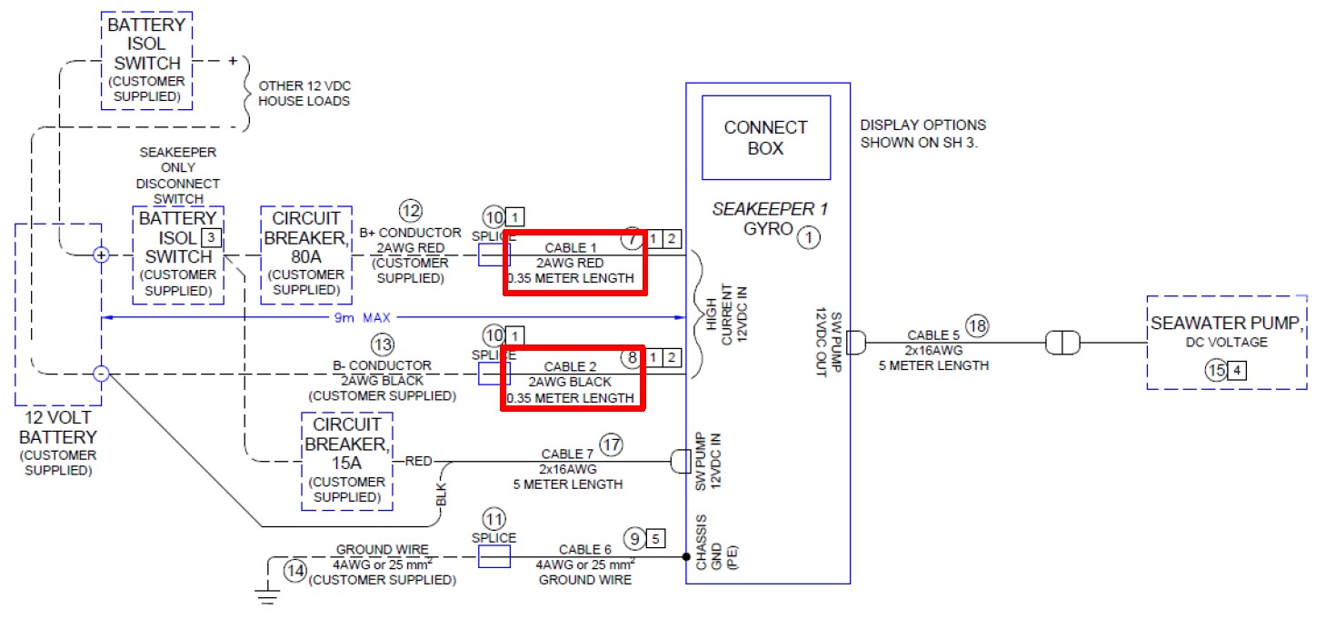
Figure 3 – Seakeeper 1 Cable Block Diagram (Drawing No. 90511) – High Current Connection

Reversing polarity on the DC power input to the Seakeeper can result in damaging the electronics in the control system.
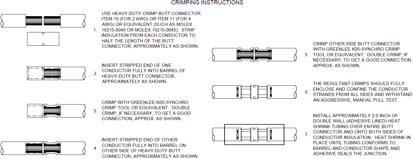
Figure 4 – High Current DC Input Crimping Instructions (Drawing No. 90511)
Seawater Pump 12 VDC Power Source Requirements
| Power Source | Battery Bank, 12 VDC, Marine, Deep Cycle |
| Voltage Range | 10 – 16 VDC |
| Current Rating | Max 15 A rating |
| Overcurrent Protection | Per pump specification, max 15 A |
Seawater Pump 12 VDC Power Input Connection Instructions
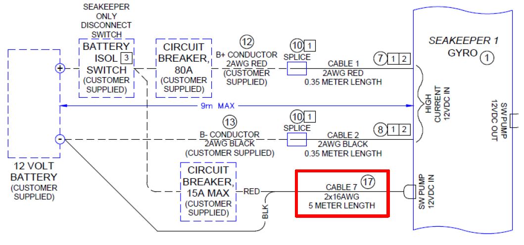
- Connect Cable 7 (P/N: 30327) to Seakeeper 1 “SW Pump DC In” as shown in Drawing No. 90511 – Seakeeper 1 Cable Block Diagram, with overcurrent protection corresponding to seawater pump selected.
- Connect the 14 AWG plus conductor (red) through dedicated overcurrent protection device (customer-supplied), maximum of 15 A, to dedicated battery isolation switch.
- The Cable 1, 2 AWG B+ conductor (red), is capable of carrying the current for both the High Current and Seawater Pump from the 12 VDC power supply to the battery isolation switch.
- Connect the 14 AWG minus conductor (black) directly to battery minus terminal or DC main negative bus.
Seawater Pump 12 VDC Power Output Connection Instructions
- Connect Cable 5 to the Seakeeper 1 “SW Pump 12 VDC Out” for DC power output to the seawater pump. Cable 5 is a 2 x 16 AWG cable, 16 ft (5 m) length, with a size 16 female Deutsch plug.
- Pumps rated at 12 VDC, 15 A maximum, customer-supplied, must be configured with a Deutsch DT series, 2-pin receptacle to mate with the connector shown in the following figure.
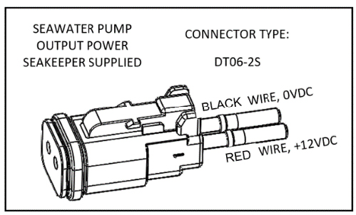
- Cable 5 must be routed and installed in the vessel from the Seakeeper 1 “SW Pump 12 VDC Out” Deutsch connector (pins end) to the DC seawater pump cable Deutsch connector (socket end).
- Connect Cable 5 plug end (socket end) to the customer-supplied receptacle end (pins end). The recommended wiring is shown in the following figure.
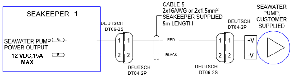
Figure 7 – Cable 5 – Seawater Pump
- Seakeeper DC Seawater Pump Assembly (P/N 30331), which is prewired for Cable 5, is available as an option with the Seakeeper 1.