Troubleshooting Checklist - Codes 256-263
Troubleshooting Checklist – Codes 256-263
1. Notes Before Beginning
Background – Fault Codes 256, 257, 258, 259, 260, 261, 262, 263 indicate a loss of communication between the Ride Software Module and the Ride Actuators. This can be a result of the Actuators not receiving correct input power (either 12 or 24 VDC, a difference in power source between the Software Module and Ride Actuators, a disconnect in cable hardware, EMI or some combination of those items.
Distribution Module Power – To clear these faults, power must be supplied to both the Software Module AND the Distribution Module. Verify that the circuit breaker and switches supplying 12/24 V power to the Distribution Module are on.
Clearing Fault Codes – For some Faults within the Ride system, in order to clear the fault and proceed with normal automatic operation, the operator must acknowledge the fault by selecting the center button on the keypad or MFD. For Codes 256-263, this is the case where the operator must acknowledge the fault.
GPS Signal Required – To clear these faults, you need correct and complete GPS signal. Therefore, if a 553, 554, or 555 fault is also present, it will not satisfy requirements and will not allow an Age Count to be cleared.
Software Updates – Update to the newest software for the troubleshooting guide below to be most relevant and up to date and helpful. See Software Update Instructions.
Compounding Fault Codes (Legacy Software) – Example: 256, 555, 570, 577, 1040. In older software versions a series of fault codes will trigger in conjunction when various Ride components are disconnected from the CAN network. When troubleshooting multiple fault codes, address codes in the following order:
- If you have codes 554 or 555 (GPS related items) please start with these first.
- Next work on 256, 257, 258, 259, 260, 261, 262, 263.
- Once 256, 257, 258, 259, 260, 261, 262, 263 are resolved, 570, 577, 1040 codes will automatically resolve.
Electromagnetic Interference (EMI) – Easiest temporary solution for troubleshooting is turn off unnecessary electrical equipment to isolate system as best as possible, this can include stereos, transducers, bow thrusters, jack plates, trim motors etc.
Actuator Replacement – When replacing an Actuator, an ‘AGE COUNT’ fault will trigger with the new Actuator connected. In addition, a ‘Controller Configuration Invalid – Code 1028’ will also trigger. The detailed screen of the 1028 will provide step by step guidance through the UI for programming the new Actuator, clearing fault codes and making Ride functional once again. (See Actuator Replacement.)
2. Diagrams for Troubleshooting
Seakeeper Ride Supplied
- Software Module
- Seakeeper Ride Proprietary CAN Bus
- Distribution Module
- Controllers
- Keypad (Optional)
Boat/Customer Supplied
- NMEA 2000 Backbone
- Multifunction Display (MFD)
- 12 V or 24 V Positive, Negative, and Ground Terminals
- 15 Amp Circuit Breaker or Fuse (25 Amp for Four Controller Systems)
- Battery Isolation Switch
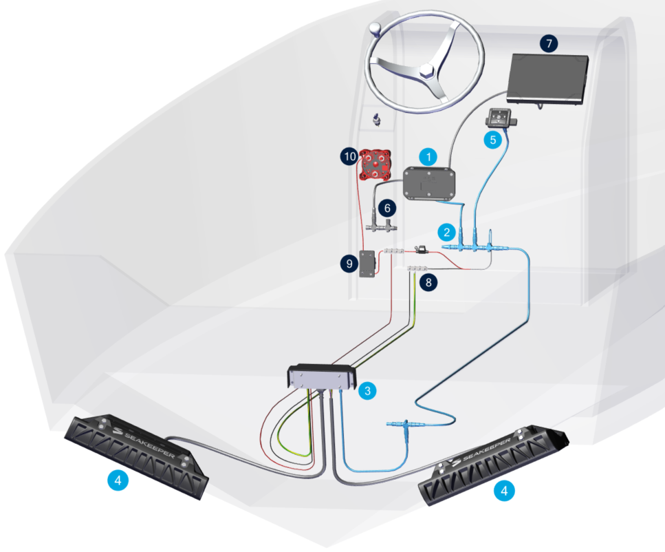
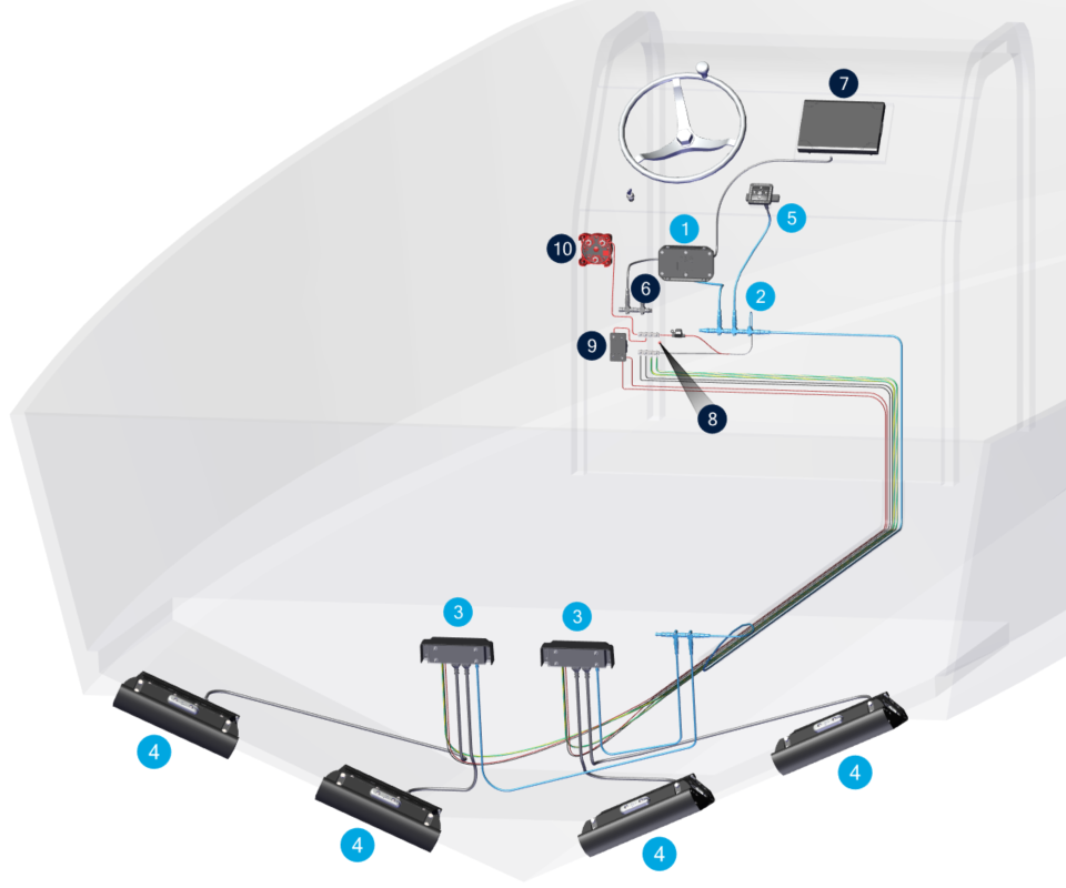
Seakeeper Ride electrical overview for two (2) and four (4) Actuator systems.
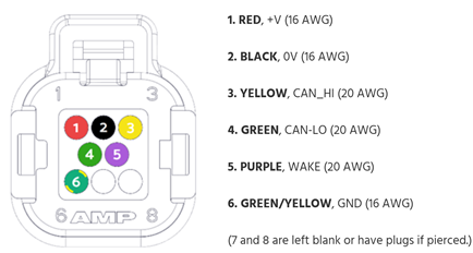
Actuator Ampseal plug pinout order.
3. Initial Checks
☐ Update to the newest software.
☐ Verify reliable GPS signal (no 554 or 555 Faults).
☐ Check that both Software Module AND Distribution Module have 12/24V power. The Distribution Module should have a circuit breaker that must be on.
A. Has Ride functioned previously?
YES → Continue to next question.
NO → Review Configuration Instructions.
☐ SPECIAL NOTE: Upon startup of Ride you should be prompted by the installation wizard. If you have arrived at the home page without proceeding through the install wizard performing, a factory reset will take you through this process step by step.
If you have replaced an Actuator and seeing the age count fault (256-263) and a 1028 fault, select the 1028 Fault and follow step by step instructions there to configure the newly replaced Actuator and enjoy one hell of a Ride.
B. Does Fault trigger on engine start and can be cleared after engine has started?
YES → Go to Battery Power section.
NO → Go to Next question.
C. Does the fault appear as soon as you turn on Ride / at Boat Power On (boat battery[ies] turned on) and will not clear?
YES →
- ☐ Are the circuit breaker and switches supplying 12/24 V power to the Distribution Module on?
- → Continue to next question.
NO, fault only occurs when other devices operate → Go to Check for Electromagnetic Interference (EMI) section.
NO, fault occurs intermittently during operation. → Go to Power and CAN Check section.
D. Does fault clear after GPS signal is acquired? –
☐ Note that a valid GPS signal must be satisfied to clear age count faults (256-263).
YES → Go to Battery Power section.
NO → Continue to next question.
E. Does Fault Trigger for multiple Actuators at the same time? (Example Port 1 256 and Starboard 1 259 ) always trigger together?
YES → Go to Power and CAN Check section.
NO → Only one Actuator fault triggers at a time. → Go to Determine Whether the Actuator Needs Replaced section.
4. Power and CAN Check
A. Inspect Distribution Module
☐ Check power and polarity at Distribution Module power plug (see Distribution Module Wiring).
☐ If there is no power here, check fuse/breaker/power source for clean 12/24 V power.
☐ The Distribution Module power cable needs to be secure in the Distribution Module. Pull on cable to ensure it is locked in place (see Distribution Module Wiring).
☐ Visually Inspect for overheating, corrosion, saltwater spray, or other damage to Distribution Module.
☐ Check Seakeeper Ride CAN Network construction – CAN cables follow sequence below.
☐ Check both Ampseal plugs for corrosion or damage.
☐ Inspect cables for strain, pinching, fraying, or moisture.
☐ Check CAN connection to Distribution Module for corrosion or damage.
☐ Check Terminator Resistor at Distribution Module end of CAN network (CAN network is item 2 in the Electrical Overview figure above).
☐ Check tee and drop to Distribution Module.
B. SM → Distribution Module (CAN)
☐ Check connector seating; verify no bent pins or corrosion.
☐ Inspect full cable length for abrasion, cuts, or compression.
☐ For confirmation, run a temporary CAN cable over the boat deck from the Ride backbone to the bilge T-connector.
C. Actuator Cables → Distribution Module
☐ Ampseal connectors are secure and undamaged.
☐ Inspect cables for strain, pinching, fraying, or moisture.
☐ Inspect, disassemble, reassemble Ampseal plug on both Actuators (link to manual with Ampseal instructions) (double check pinning matches diagram).
D. Seakeeper Ride CAN Network
☐ Tip: If you have a Keypad and it is functional, you know the Software Module is still communicating.
On Seakeeper Ride CAN Network (not NMEA 2000 backbone):
☐ NMEA plug fully seated in ‘SK’ port on Software Module.
☐ NMEA cable is connected to drop location on Seakeeper Ride CAN network.
☐ Connections are straight and secure on all:
- ☐ Cable ends
- ☐ Tees
- ☐ Terminator resistors
- ☐ Modules throughout the network (Software Module, Distribution Module, Keypad)
☐ No bent pins/corrosion.
☐ Cable not damaged.
☐ NMEA 2000 network is not cross connected to Seakeeper Ride network (CAN Stats page).
Rebuilding Network for Diagnostics:
☐ With CAN network recreated on the deck for easy inspection, connect the Distribution Module and Actuators.
☐ Use as much new equipment as possible (new NMEA cables, tees, and resistors; spare Distribution Module if available; spare Actuators if available).
E. Fault Combinations – Additional Tips
Two (2) Actuator System –
☐ If both Actuators are age count faulted, most likely either the Seakeeper Ride CAN network has issues or power is not going Distribution Module.
- ☐ If after exhausting this section, power is verified, and CAN network has been checked and reconstructed, likely the Distribution Module needs replaced.
- → Follow the Warranty & Replacement Procedure section. A Ride Support specialist will determine whether replacement components are required.
☐ If only one (1) Actuator is age count faulted, see Determine Whether the Actuator Needs Replaced section.
Four (4) Actuator System –
☐ If all four (4) Actuators are age count faulted, most likely either the Ride CAN network has issues or power is not going to BOTH Distribution Modules.
☐ If two (2) out of four (4) triggered (both of those two (2) are connected to the same Distribution Module), most likely that single Distribution Module is not getting power or the Distribution Module is faulty.
- ☐ Try switching the two (2) Actuators showing age counts to another Distribution Module.
- Do the faulting Actuators switch from one pair to another (e.g., Port1 & Port2 Age Count become Starboard1 & Starboard2 Age Count)?
- YES → Distribution Module likely needs replacement. Follow the Warranty & Replacement Procedure section. A Ride Support specialist will determine whether replacement components are required.
- NO → Go to Determine Whether the Actuator Is Faulty section and follow procedure for both Actuators.
☐ If only one (1) Actuator is age count faulted, go to Determine Whether the Actuator Needs Replaced section.
5. Battery Power
If the Distribution Module power cable is connected to an engine start battery, the current draw during engine start might lower voltage at the Distribution Module enough to trigger a fault.
☐ Check for battery power during engine start. Ensure batteries are fully charged.
☐ If fault still occurs on engine start, consider changing battery power source for Distribution Module power. Ride recommends connecting to a house battery to avoid this issue. It is recommended that the Software Module power also comes from the same source as the Distribution Module.
Depending on how Ride is wired, it could draw power for the Distribution Module and Software Module in different locations with consequences to its operation. To eliminate fault triggers on engine start:
☐ Ensure batteries are fully charged
☐ Rewire Distribution Module and Software Module to draw power from the same location (link to electrical drawings). Seakeeper Ride recommends pulling power from house batteries which are not responsible for engine starting to prevent this fault from occurring.
☐ Because Ride needs a valid GPS source, if the power up sequence of the boat has Ride booting up prior to GPS signal, it is possible that the fault will not clear until GPS signal is acquired. Consider altering boat electronic package installation details to have the GPS source and NMEA 2000 bus power on at the same time as or before Ride to avoid this fault.
6. Determine Whether the Actuator Needs Replaced
☐ Inspect and disassemble, reassemble Ampseal plug on bad Actuator side (link to manual with Ampseal instructions) (double check pinning matches diagram).
☐ Swap Actuator connections on Distribution Module – Actuator assignment is NOT dependent on Distribution Module ports. Swapping sides will help determine if the Distribution Module is bad.
A. Does faulty Actuator fix with Distribution Module swap (e.g. Fault 256 – Port1AgeCount changes to 259 – Starboard1AgeCount)?
YES → The opposite Actuator becomes faulty. (i.e. if Starboard 1 is faulty, ports are swapped on Distribution Module and then Port 1 becomes faulty). → Replace Distribution Module.
NO → Faulty Actuator STAYS faulty (i.e. if Starboard 1 is Faulty, ports are swapped on Distribution Module, and Starboard 1 is still faulty). → Do final checks below. If nothing is evident, the Actuator may need to be replaced.
B. Final checks before determining if the Actuator needs replaced:
☐ Actuator pinout is correct.
☐ All connectors are secure –
- Gently tug on Distribution Module power cable and Actuator cables to ensure they are seated completely.
- All NMEA wires, tees, and resistors are connected straight and securely.
☐ No wiring damage is found.
☐ EMI sources mitigated.
☐ Configuration is correct (satisfied).
C. If the fault persists:
Follow the Warranty & Replacement Procedure section. A Ride Support specialist will determine whether replacement components are required.
7. Check for Electromagnetic Interference (EMI)
A. Reproduce the Fault
☐ Operate high-draw/noisy devices (jack plate, windlass, trim cylinders, pumps, etc.). Turn devices on and off. Sometimes EMI can be heard in speakers or other sensitive equipment.
☐ Operate Transducers with hull in the water.
☐ Note whether codes appear consistently during operation of another elerical device.
B. Resolve the Fault
☐ Confirm Seakeeper Ride wiring is not bundled with high-current wiring.
☐ Separate Ride wiring from jack plates, windlass systems, trim tabs, trolling motors, etc.
☐ If faults trigger during operation of specific other accessories, move Ride cables to a different location to increase distance between Ride cables and equipment which is causing the fault.
☐ Cross cables at a 90-degree angle if they must be routed past each other.
☐ If cables cannot be routed to a different location the equipment which is generating the EMI might be mitigated with a ferrite bead; increased insulation, including EMI tape; or verifying all equipment is grounded correctly.
☐ Contact Seakeeper Ride if problem cannot be resolved with these adjustments.
8. Warranty / Replacement Procedure (If Needed)
Gather the following:
- ☐ Software Module serial number.
- ☐ Photos of wiring layout/routing (when applicable).
- ☐ List of electrical devices active when the fault occurs (when applicable).
- ☐ Notes on any intermittent communication behavior.
☐ Open a Ride Support case documenting all findings.
☐ Ensure troubleshooting details are included in the case.
☐ If a component is confirmed defective, a replacement will be issued per Seakeeper warranty policy.