Mechanical Installation Manual (750-1500)
7. Prepare Wedge Pack Introduction
Preparing the Wedge Pack Introduction
This portion of the installation will require the Wedge Pack hardware kit illustrated in Section 4.
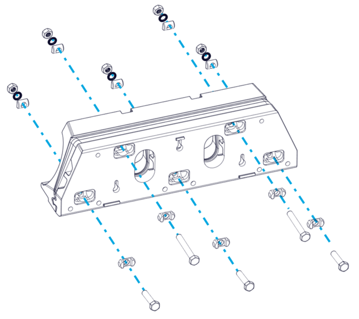
To begin the Transom Plate must be assembled. This requires selecting the correct length bolts as indicated by the transom angle table above.
- Place a Cylindrical Washer for Hex Head on each bolt, with the flat side on the head of the bolt.
- Install the bottom three (3) M8 bolts selected based upon the total Wedge Plates in use. See Table 2 to determine if the 35 mm or 40 mm bolts must be used. (Quantity four [4] bolts for 525 Controllers and five [5] bolts for 750 Controllers.)
- Install the top two (2) M8 bolts selected based upon the total Wedge Plates in use. See Table 3 to determine if the 55 mm or 75 mm bolts must be used. (Two [2] top bolts and four [4] bottom bolts for 525 Controllers. Four top bolts and five [5] bottom bolts for 750 Controllers.)
- At this point, the bolts must be inserted into the Transom Plate with Cylindrical Washer for Hex Head cylinder in each of the five (5) locations. (Quantity six [6] bolts for 525 Controllers and nine [9] bolts for 750 Controllers.)
- Cover the bolt head with the supplied self adhesive backed plastic caps. The caps will prevent adhesive leak by around the bolts and allow for tuning the equipment by adding or removing wedges once installed and adhesive has cured.
7.1 Determine Wedges
Based on Table 3 and the transom angle determined in Section 6, compile the Transom Plate, Actuator Plate, Wedge Pack Hardware kit and appropriate wedges for each controller. It is possible that the hull has different angles for each Controller location.
- Stack the proper number of Wedge Plates on top of the Transom Plate using the bolts to guide them into place. The locking tabs of the Wedge Plates will face the Transom Plate and secure the correct orientation.
- Place the Actuator Plate on top of the Wedge Plates using the bolts to guide them into place. The tabs of the Actuator Plate will match with the grooves of the Wedge Plates to complete the Wedge Pack Assembly.

7.2 Secure Actuator Plate
- Locate the following pieces:
- Qty five (5) M8 Cylindrical Washers (Qty six [6] for 525 Controllers and nine [9] for 750 Controllers.)
- Qty five (5), M8 Wedge Lock Washers (Qty six [6] for 525 Controllers and nine [9] for 750 Controllers.)
- Each washer has 2 components.
- Qty five (5), M8 Nuts (Qty six [6] for 525 Controllers and nine [9] for 750 Controllers.)
- Each washer has 2 components.
- Insert all the cylindrical washers, flat face out, onto each of the bolts within the milled pockets on the Actuator plate.
- Insert all the wedge lock washers onto each of the cylindrical washers.
- Thread all the nuts onto each of the bolts of the assembly hand tight.
- Check the bolt length is sufficient to engage all threads of the nuts.
- Tighten nuts to 130 in-lbs (14.7 N-m)
- Adhere Bolt Covers.

Note: Be sure to use the correct bolt length. Incorrect bolt length may result in insufficient thread engagement or the inability to attach the Seal Plate in later steps.
Note: Insert the bolts from the Transom Plate side NOT the Actuator Plate side. Incorrect bolt direction will result in inability to adjust the Wedge Pack angle after installation and likely cause interference when placing the Wedge Pack on the transom.
Note: All variables to be torqued to in-lbs NOT ft-lbs.
Repeat this process for all Controllers to create the Wedge Pack Assemblies before moving on.