Actuator Replacement and Friction Check
Check Actuator Friction & Add Friction Gasket
Introduction
This document is a guide for replacing the Seakeeper Ride Actuator, checking Actuator friction, and adding a Friction Gasket if need.
The Seakeeper Ride design utilizes a round Actuator clamped in place by the Seal Plate and Actuator Plate. This design allows for flexibility in installations, easy maintenance, reducing stocked parts, and preventing damage if underwater objects are struck. The friction generated to hold the Actuators in place must be checked as part of routine maintenance. To improve long-term friction, adjustments to the Actuator Plate parts have been made. In many cases, it is possible to update your parts to adhere to changes. This guide will assist in assessing the friction on the Actuator and making upgrades, if necessary.
This procedure will require the boat engines shut down, access to the Controllers, and the Seakeeper Ride system turned on and in manual mode. Manual mode will provide better understanding of the Blade position with feedback of on the MFD.
Actuator Replacement
Preparation
- Turn off the boat, including the engines and the Seakeeper Ride system.
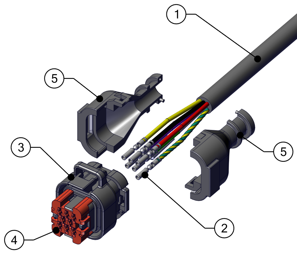
- Controller/Actuator Cable
- Pins
- Ampseal Plug Housing
- Ampseal Wedge Lock
- Ampseal Backshell Half
- Cut off current shrink wrap and unclip the plastic casing protecting the Actuator wires (Ampseal Backshell, item 5 in the figure above).
- Lift up the red cap (Ampseal Wedge Lock, item 4 in the figure above) by gently prying open the red arch-shaped clips while pushing the red cap up. After the red cap is lifted, fully remove it by pulling and rocking back and forth slightly.
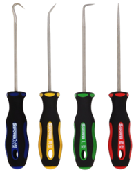
- Use a pick tool to gently move the black plastic clips holding the pins and pull the pins out (remove item 2 from item 3 in the figure above).
- Loosen the Cable Gland from inside the hull to ensure the cable will be able to move freely.
See this video from Ampseal for best practices.
Removal
Note: For Ride 750-1500 systems, the front Blade Anode and bonding wires attached to the Blade, Actuator, and Seal Plate will need to be removed in order to remove the Blade and Seal Plate.
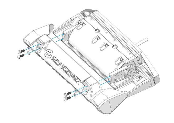
- Remove the four (4) M8-1.25 x 20 mm Hex bolts holding the Blade in place.
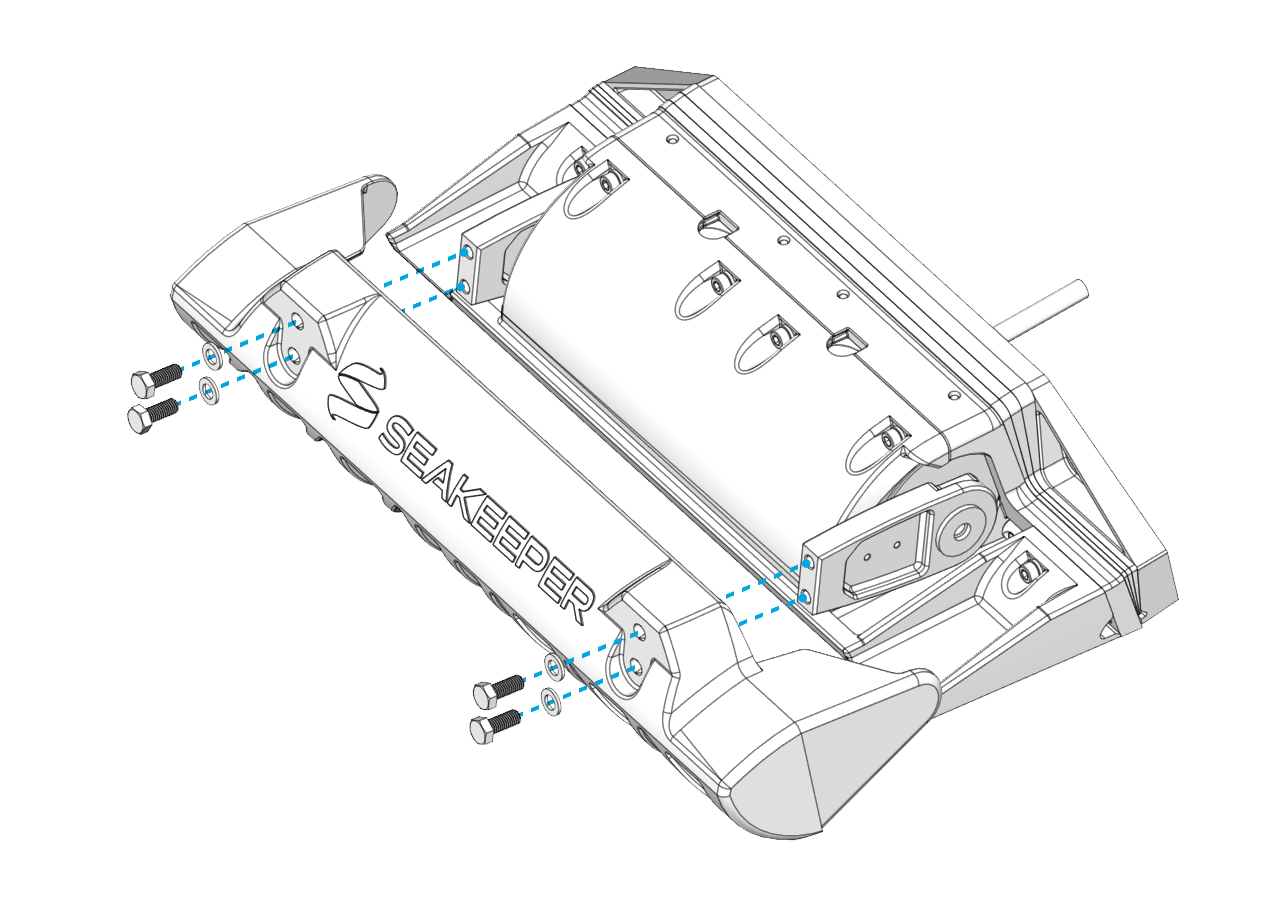

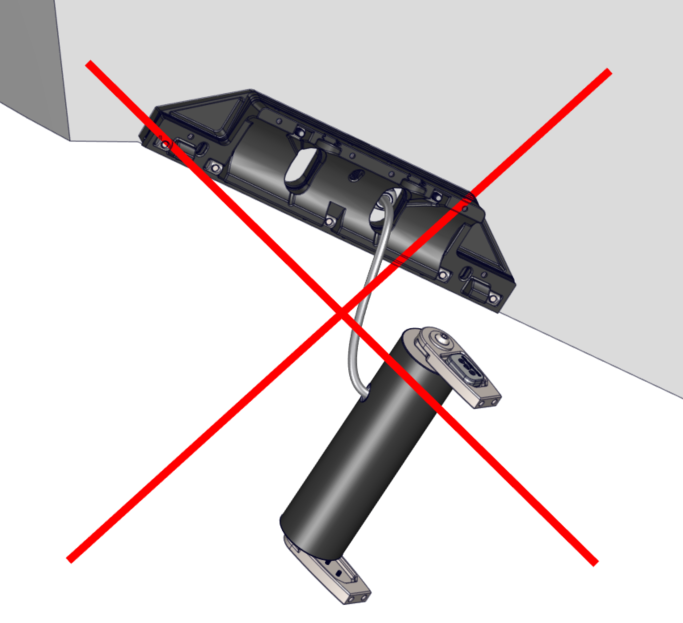
ATTENTION: Once the Seal Plate is removed, the Actuator will be unsupported. DO NOT allow the Actuator to hang by the cable. Use a table, strap, or some other method to support the weight of the Actuator.
- Remove the Seal Plate
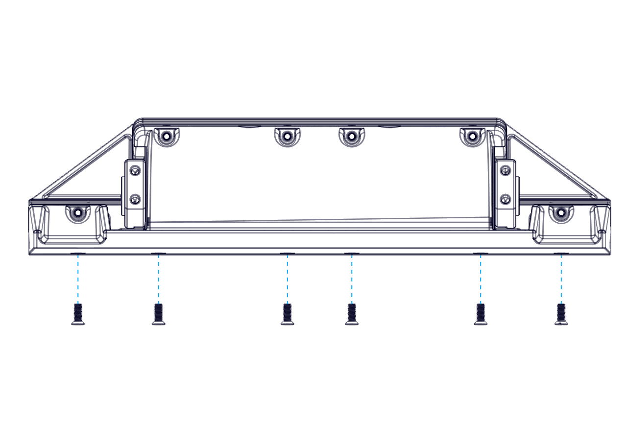
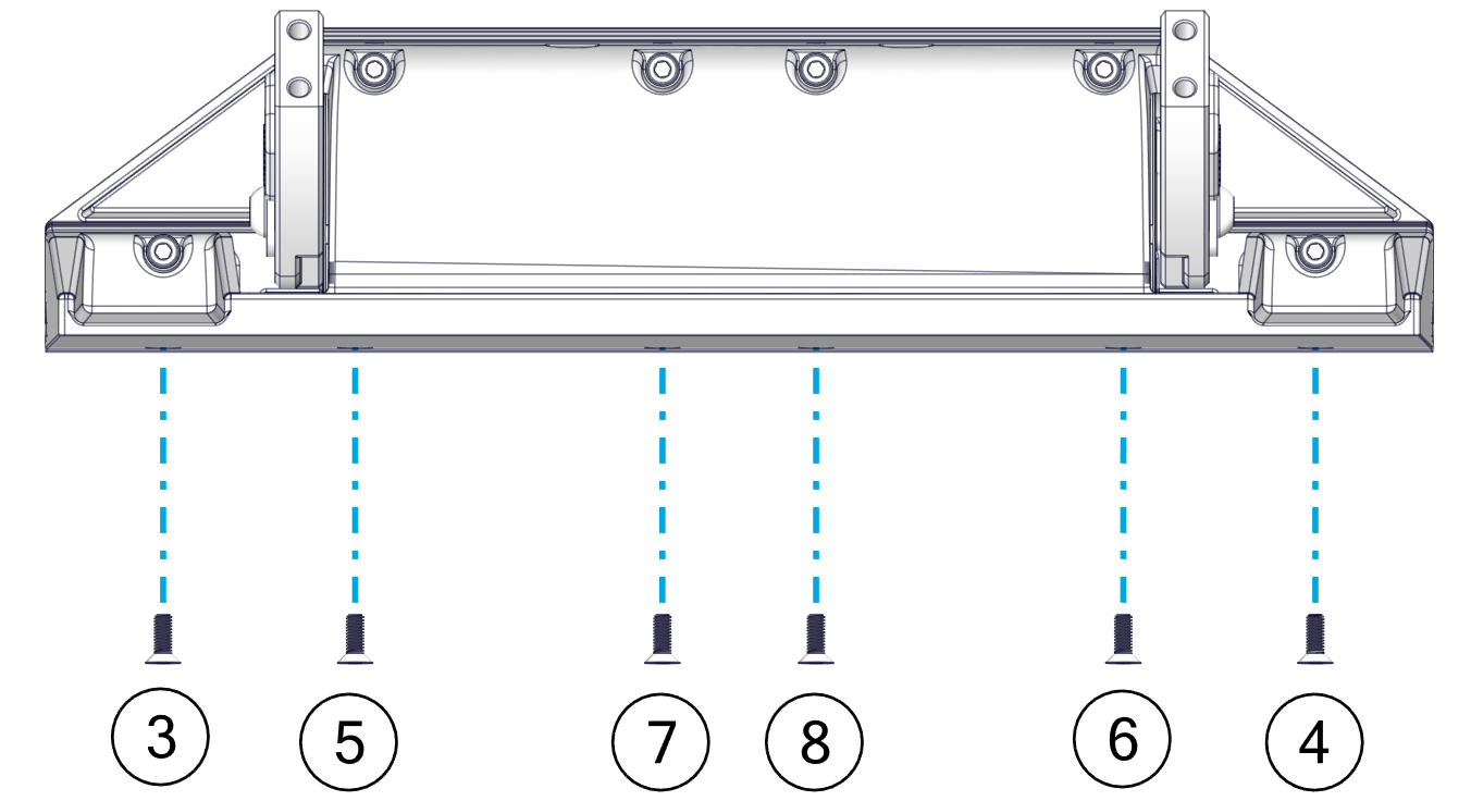
- Remove the six (6) M6-1.0 x 16 mm Flat Head Socket Cap Screws from the bottom edge of the Seal Plate. (Note: The Seakeeper Ride 600 system will have eight (8) screws).
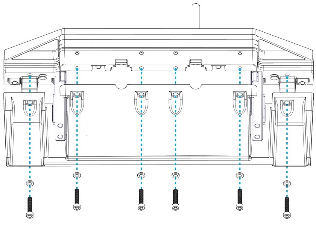
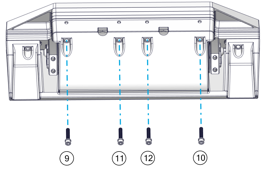
- Remove the six (6) M6-1.0 x 30mm Socket Head Cap Screws from the top face of the Seal Plate. (Note: The Seakeeper Ride 600 system will have eight (8) screws).
- Remove the Seal Plate and Actuator by pulling the cable out through the gland.
Rebuild
Apply thread locker to all hardware during rebuild (Vibra-Tite 132 for Ride 450-600 systems and Vibra-Tite VC-3 for Ride 750-1500 systems). Make sure to tighten each fastener to the specified torque. Torque values vary by Ride model.
Torque Specifications Ride 450-600
Torque Specifications Ride 750-1500
- Place the new Actuator in the Actuator Plate. Ensure the Actuator is in same orientation as it was mounted prior to removal.
- Set the Seal Plate back over the Actuator and secure it in place with two (2) M6-1.0 x 30mm Socket Head Cap Screws in wing positions. (Note: The Seakeeper Ride 600 system will have four (4) screws).
Apply Torque two (2) times to ensure fasteners are seated.

- Secure the Seal Plate bottom with six (6) M6-1.0 x 16 mm Flat Head Socket Cap Screws from the bottom edge of the Seal Plate and apply thread locker to the screws. (Note: The Seakeeper Ride 600 system will have eight (8) screws).
Apply Torque two (2) times to ensure fasteners are seated.
- Secure Seal Plate top with the four (4) M6-1.0 x 30mm Socket Head Cap Screws from the top face of the Seal Plate, apply thread locker to screws. Apply Torque two (2) times to ensure fasteners are seated.
- Replace the Blade with four (4) M8-1.25 x 20 mm Hex bolts, apply thread locker. Torque to 80 in-lbs (9 N-m). Apply Torque two (2) times to ensure fasteners are seated.
- Tighten the cable gland to ensure equipment is restored and water tight.
- Re-pin the Actuator following the instructions in Section 8.3 of the Electrical Installation Manual. Make sure to follow the wiring diagram for correct pin placement.
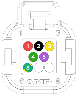
1. RED, +V (16 AWG)
2. BLACK, 0V (16 AWG)
3. YELLOW, CAN_HI (20 AWG)
4. GREEN, CAN-LO (20 AWG)
5. PURPLE, WAKE (20 AWG)
6. GREEN/YELLOW, GND (16 AWG)
(7 and 8 should be plugged.)
Reprogram
The new Actuator will need to be programmed and the Blade zeroed. Note: Exact fault numbers and labels may be different depending on the system and Actuator being replaced, but the process should be the same.
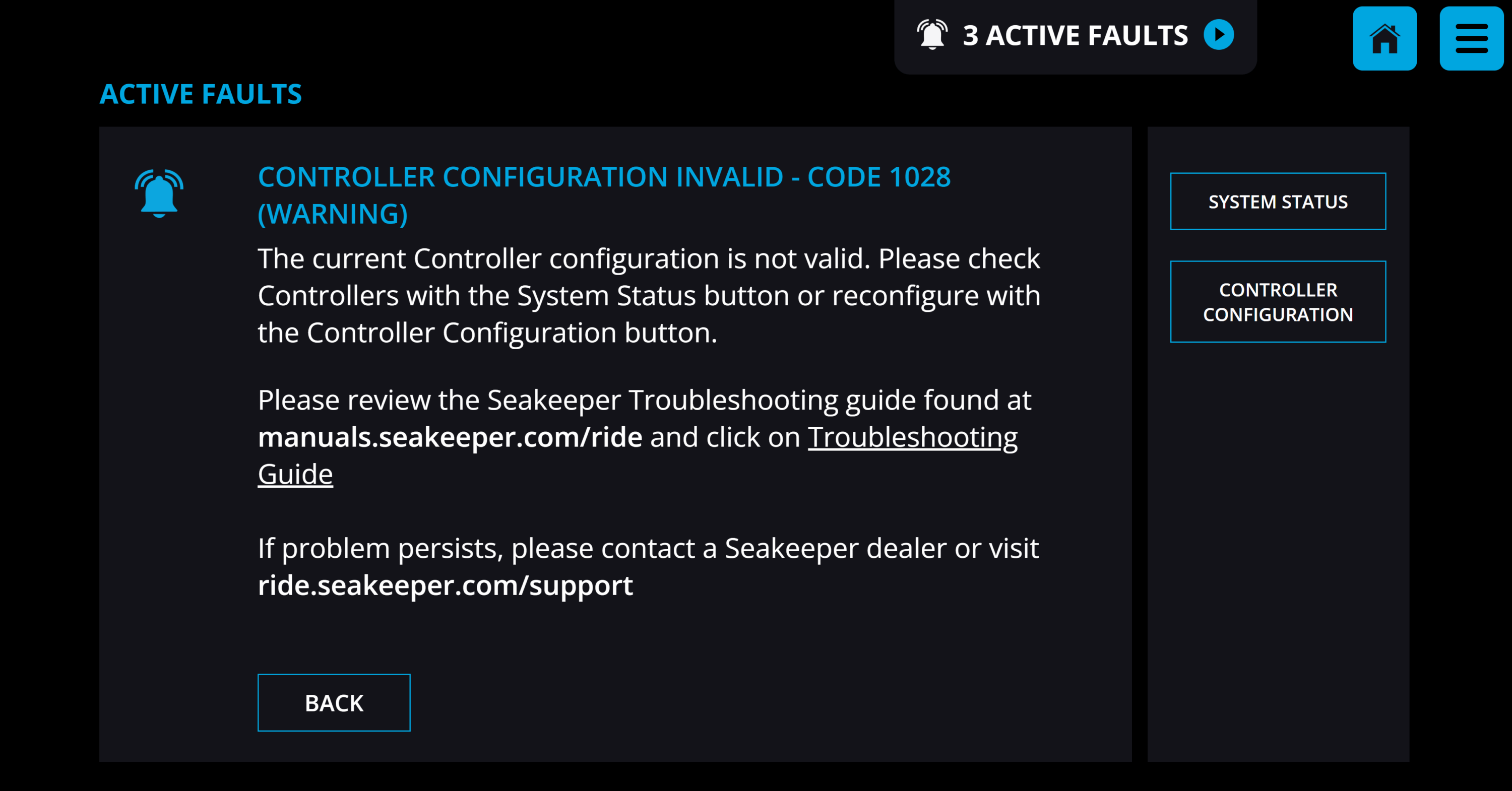
- Turn on the Seakeeper Ride system. The Home Screen on the MFD should show faults in the top of the screen.
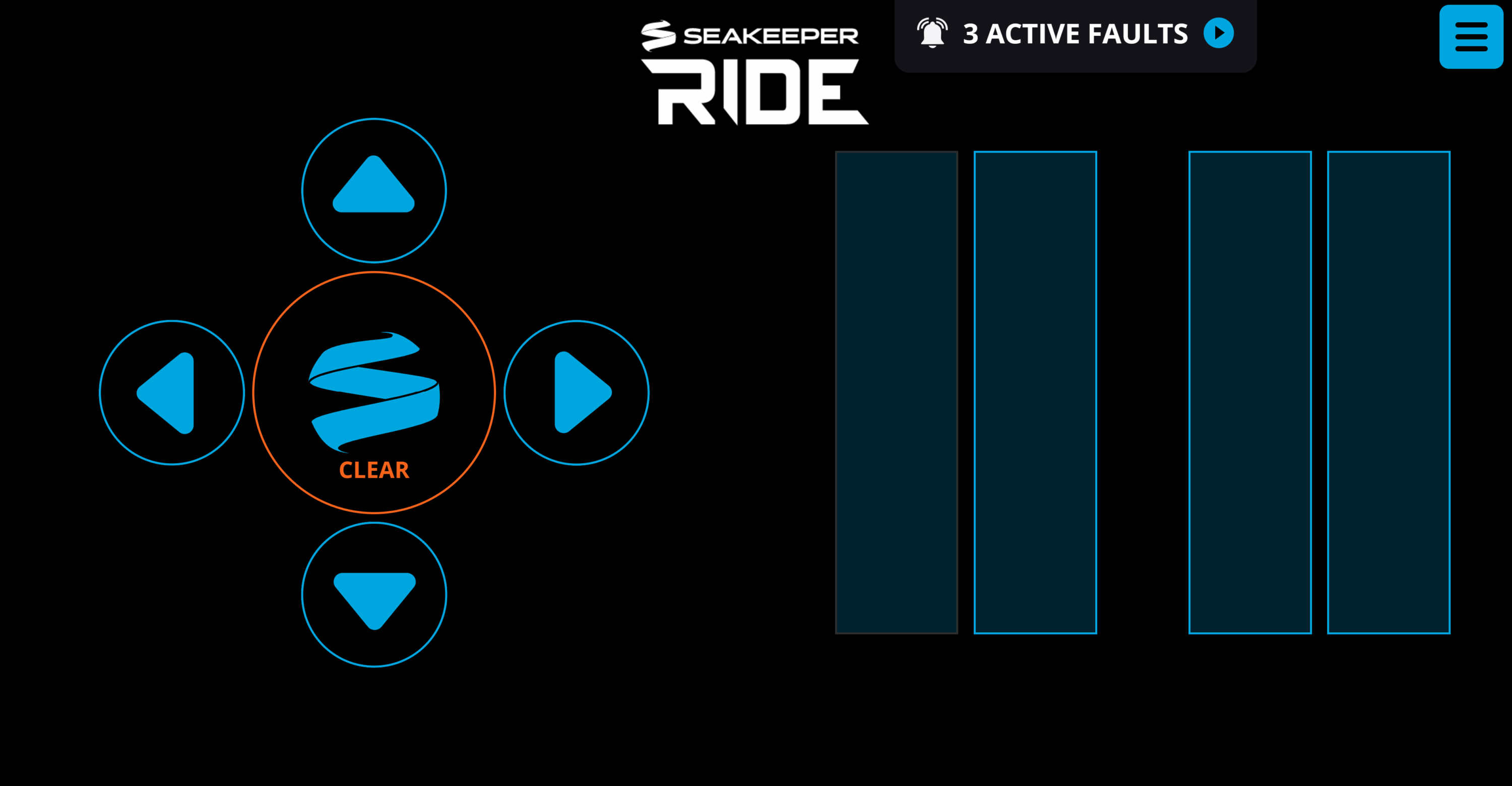
- Open the active faults by pressing the notification at the top of the screen. Alternatively, press the menu button in the top right corner of the screen and navigate to the Faults page.
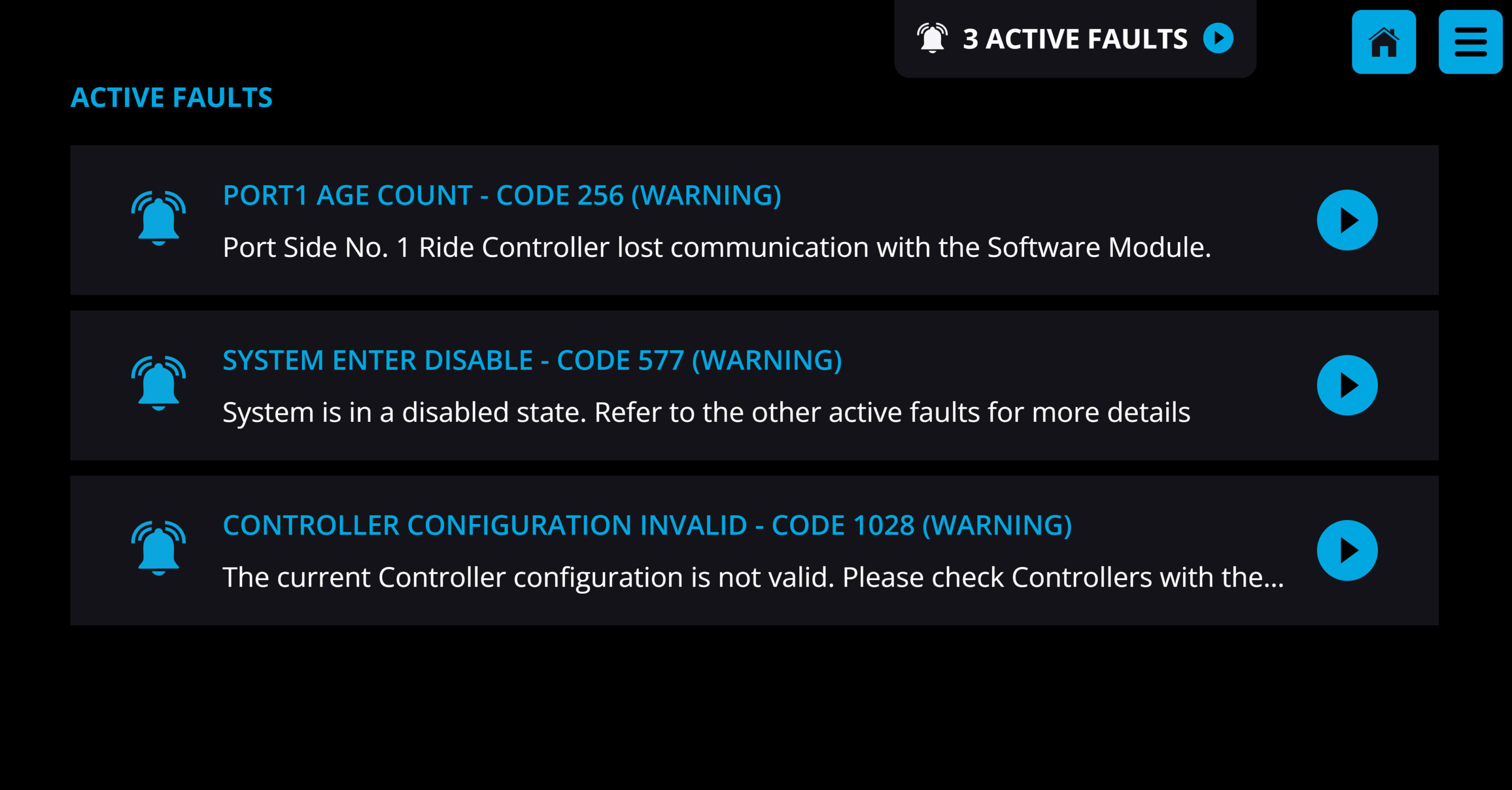
- Find the Configuration fault (Code 1028 in example shown), which will contain a link ‘CONTROLLER CONFIGURATION’ to program the new Actuator. Click this link and follow on screen prompts.
- Follow the instructions for Controller Zeroing and Diagnostics for both port and starboard Controllers (all Controllers will be reconfigured).
- If fault codes remain after configuration, restart the Seakeeper Ride system by turning off power to both the Software Module and Distribution Module(s), wait for 20 seconds, and re-power on the system.
If the programming link is not found, perform a Factory Reset in the Service Menu to fully reconfigure the system.
Checking Actuator Friction
1. Ensure you have access to the Controllers. If the boat is in the water, this may not be possible. The boat may need to be hauled out of the water or trailered for the full procedure.
2. With the boat hauled out of the water or on a trailer, be sure engines are turned off. Turn the Seakeeper Ride system on.
3. Select Manual Mode on the Seakeeper Ride application.
4. Check that no fault codes are present on the Seakeeper Ride system, which ensures the Actuators will hold the Blade in place.
5. Go to each Controller individually and attempt to move the Blade up and down by hand. Do not use excessive force, approximately 5lbs (2.2 kg) is sufficient.
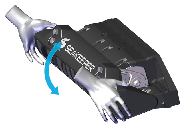
6. The Blade should be ‘locked’ in place. If there is no movement, the equipment passes this check.
7. If the Blade and the silver portion on the side of the Actuator (surface 2 below) move together while the black outer rim of the Actuator (surface 1 below, highlighted in red) stays in place, review procedure and ensure the Seakeeper Ride system is turned on, configured and in manual mode.
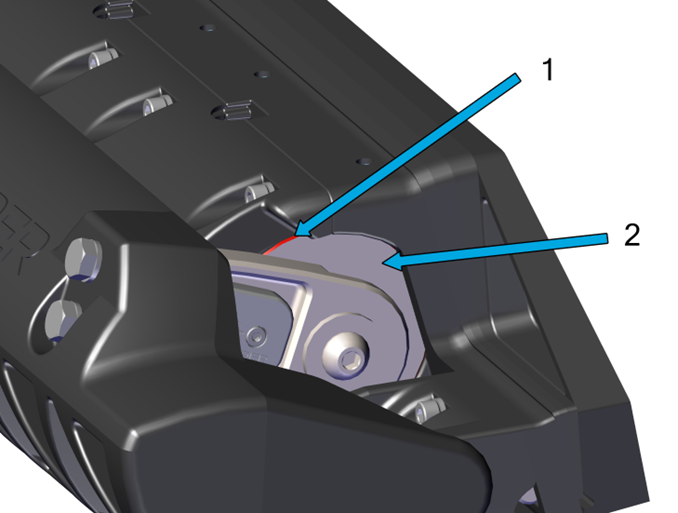
If the Actuator and Blade are fixed in relation to one another and both move in relation to the Seal Plate (surface 1, surface 2, and the Blade all move together), follow instructions on Adding Friction Gasket.
Adding Friction Gasket
To increase the Actuator friction within the Seal Plate and maintain the optimum performance of Seakeeper Ride, add a Friction Gasket using the following steps and reassemble with Vibra-Tite 132 thread locker and the updated torque values.
Preparation
- Turn off the boat, including the engines and the Seakeeper Ride system.
- Remove the four (4) M8-1.25 x 20 mm Hex bolts holding the Blade in place.
- For installations where the Actuator cable is routed through the Wedge Pack, loosen the cable gland from inside the hull and ensure there is some slack in the cable to allow the Actuator to be pulled out a few inches from the Wedge Pack.
- Remove the Seal Plate
- Remove the six (6) M6-1.0 x 16 mm Flat Head Socket Cap Screws from the bottom edge of the Seal Plate. (Note: The Seakeeper Ride 600 system will have eight (8) screws).
- Remove the six (6) M6-1.0 x 30mm Socket Head Cap Screws from the top face of the Seal Plate. (Note: The Seakeeper Ride 600 system will have eight (8) screws).
- Pull Actuator off the Actuator Plate far enough to provide access to Actuator Plate. Support the Actuator by hand or with a table or lifting strap. Do not allow the Actuator to hang from the cable. Make note of cable routing side and Torque Arm position.
- Clean the Actuator Plate by wiping it with a clean rag. Remove anti-fouling paint or other materials with acetone or denatured alcohol. Cleaning the SMC material will assist in holding the friction gasket in place.
Friction Gasket Application
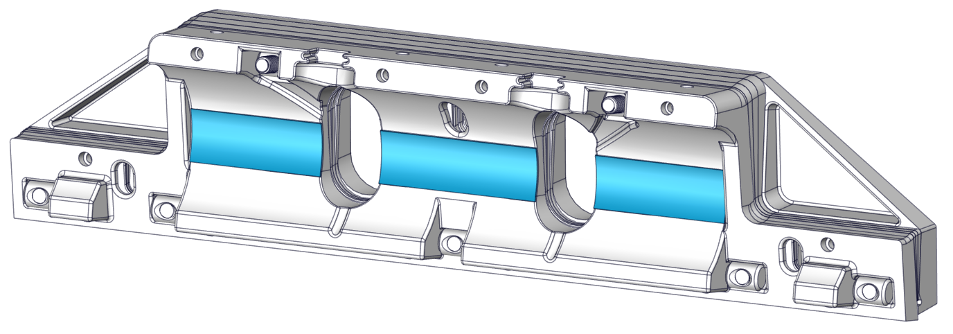
- Peel the adhesive protecting strip off of the friction gasket.
- Press the adhesive coated side of friction gasket to Actuator Plate at mid-height across the mating surface of the Actuator, as shown below.
- Cut away excess friction gasket if Actuator cable is routed through the Wedge Pack.
Rebuild
- Reset Actuator in place against the friction gasket in the Actuator Plate. Ensure the Actuator is in same orientation as it was mounted prior to removal.
- Set the Seal Plate back over the Actuator and secure it in place with two (2) M6-1.0 x 30mm Socket Head Cap Screws in wing positions. Apply Vibra-Tite 132 thread locker to the screws. Torque screws to 60 in-lbs (6.8 N-m). (Note: The Seakeeper Ride 600 system will have four (4) screws). Vibra-Tite 132 replaces the previously-specified thread locker.
Apply Torque two (2) times to ensure fasteners are seated.
- Secure the Seal Plate bottom with six (6) M6-1.0 x 16 mm Flat Head Socket Cap Screws from the bottom edge of the Seal Plate and apply Vibra-Tite 132 thread locker to the screws. Torque screws to 60 in-lbs (6.8 N-m). (Note: The Seakeeper Ride 600 system will have eight (8) screws). Torque of 60 in-lbs (6.8 N-m) is 20% greater than previously specified.
Apply Torque two (2) times to ensure fasteners are seated.
- Secure Seal Plate top with the four (4) M6-1.0 x 30mm Socket Head Cap Screws from the top face of the Seal Plate, apply Vibra-Tite 132 thread locker to screws. Torque screws to 60 in-lbs (6.8 N-m).
Apply Torque two (2) times to ensure fasteners are seated.
- Replace the Blade with four (4) M8-1.25 x 20 mm Hex bolts, apply Vibra-Tite 132 thread locker. Torque to 80 in-lbs (9 N-m). Apply Torque two (2) times to ensure fasteners are seated.
- Tighten the cable gland to ensure equipment is restored and water tight.
Reprogram
Because the Blades and Actuator have been removed and reattached, the Seakeeper Ride system will need to proceed through the Blade zeroing steps of the service menu.
- Turn on the Seakeeper Ride system.
- From the MFD, select manual mode and from the menu, select the Service Menu. The service pin to re-zero is 339037.
- Follow the instructions for Controller Zeroing and Diagnostics for both port and starboard Controllers.
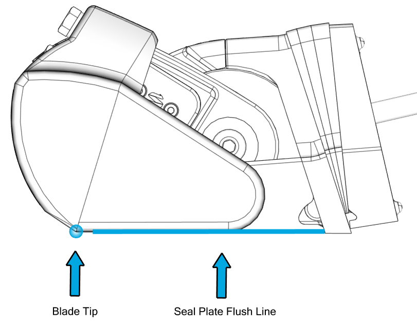
- Zeroing means setting the bottom tip of the Blade flush, or in line with the Seal Plate. The Blade should not sit low where it will capture water or high which will result in diminished system response time and authority.
Retest
Now that you have completed the procedure please return to the Checking Actuator Friction instruction to ensure the friction gasket is functioning as intended.