Configuration Instructions
Configuration Instructions
1. Introduction
Updated 4/21/26
Following installation, the Seakeeper Ride system must be configured prior to operation. This process is performed by the Original Equipment Manufacturer (OEM/boat builder) or a professional Seakeeper certified installer if they performed the installation.
Note: Scan the QR code below to access Seakeeper Ride BILT 3D instructions. BILT App will assist in familiarization with the Seakeeper Ride components and includes a specific section for configuration.


ATTENTION! Changing these critical settings can render the system non-functional and create an unsafe operating condition. Please proceed only if you have read and understand this manual in full.
ATTENTION! Advanced Mode configurations should only be changed under extenuating circumstances, such as replacing system components or if an incorrect calibration has been confidently diagnosed.
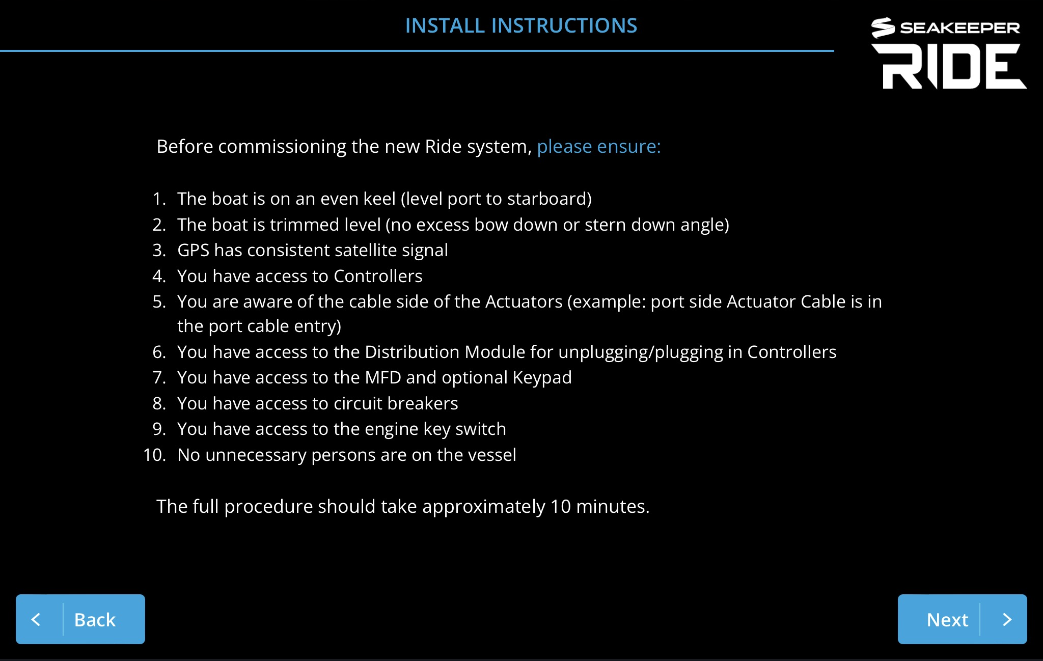
For Seakeeper Ride systems installed by end users, follow the steps below to configure your new system. The full procedure should take approximately 10 minutes if the boat is in a proper location before starting.
After following both the Mechanical and Electrical installation instructions, begin configuring by ensuring the following:
- The boat is on an even keel (level port to starboard)
- The boat is trimmed level (no excess bow down or stern down angle)
- GPS has consistent satellite signal
- You have access to Controllers (If the boat is in the water this may not be possible, and therefore the boat may need to be trailered for the full procedure)
- You are aware of the cable side of the Actuators (example: port side Actuator Cable is in the port cable entry)
- You have access to the Distribution Module for unplugging and re-plugging in Controllers
- You have access to the MFD and optional Keypad
- You have access to circuit breakers
- You have access to the engine key switch
- No unnecessary persons are on the vessel
2. Software Module Switches
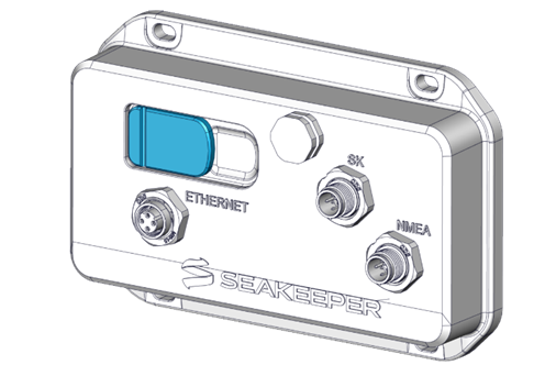
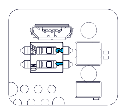
For Seakeeper Ride to connect properly to the Multifunction Display (MFD), the switches on the Software Module must be in the correct positions. Access the switches by removing the rubber covering on the upper left side of the Software Module.
Do not move Switch 2. Follow the table below to configure Switch 1 based on the MFD brand. The ‘on’ position is to the left.
| Garmin*, Raymarine, Furuno | Switch 1 Off |
| Simrad, Lowrance, B&G, Humminbird** | Switch 1 On |
*Note: When using Garmin Blue Net 30 adapters to convert from legacy Garmin Marine Network cables to Garmin BlueNetTM devices will require Switch 1 to be in the On position for correct functionality.
**See Seakeeper Ride MFD Compatibility – Seakeeper Manuals for notes on Humminbird compatibility.
Simrad: NSO and NSS Evo3 models: Software 20.1; NSS Evo3S: Software 20.0.2; GO models: Software 20.0.1. When connecting Simrad NSS4, the Seakeeper Ride app may not automatically populate. Follow these instructions if you do not see the app.
3. First Installation
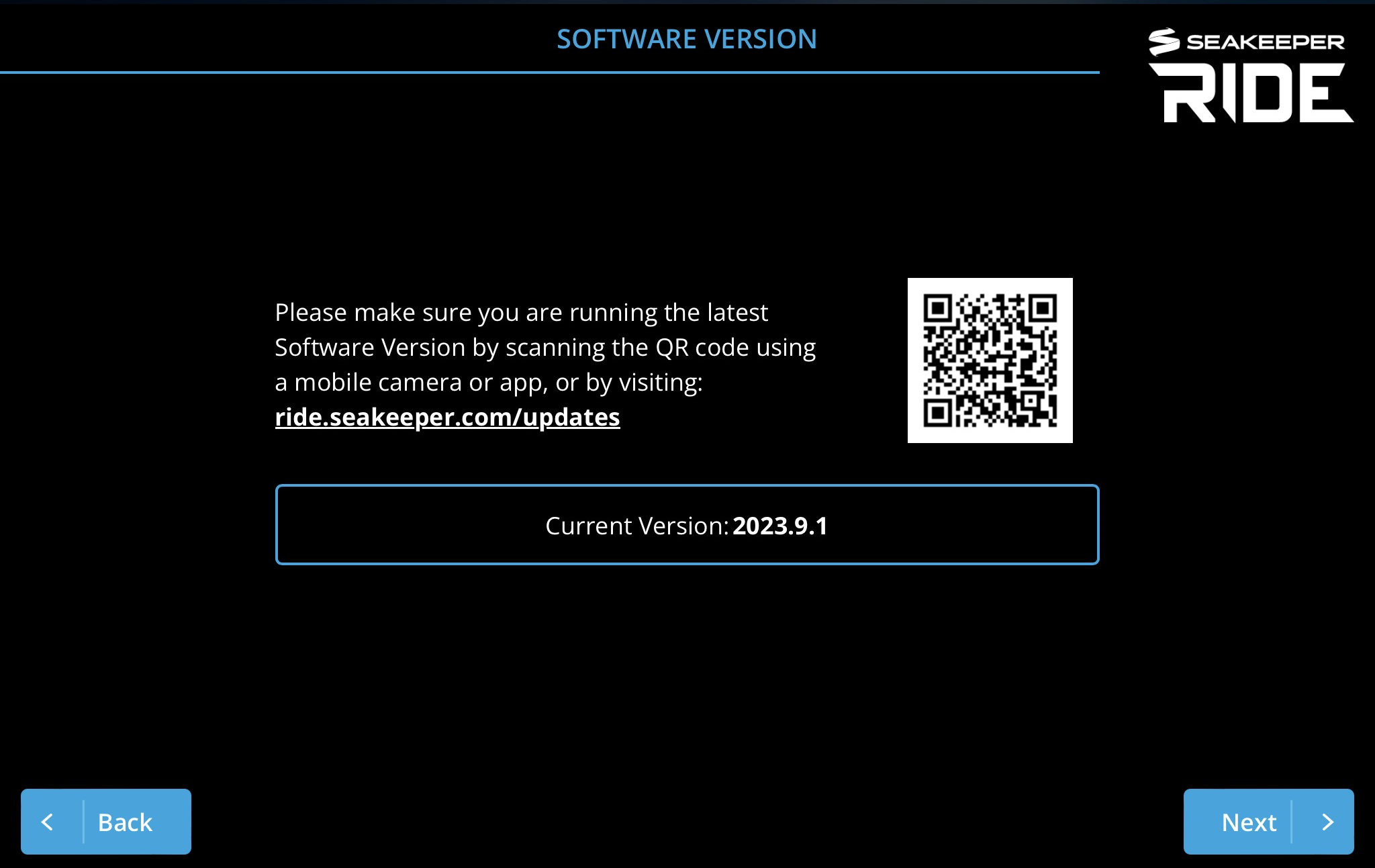
The following instructions are for Software Version 2023.9.1 and newer. If you have older Software, please update as soon as possible by downloading and following instructions here. https://ride.seakeeper.com/support/software-updates/
If you cannot update your software, please go to Legacy Configuration Procedure for step-by-step instructions on Configuring older Software.
These settings all must be entered and completed in preparation for using Seakeeper Ride. The following information details each system status screen item, what they mean and how they affect the Seakeeper Ride system.
If this is the first time operating the Ride system and you are not presented with the welcome screen to match this guide, you must select Menu, Service, Factory Reset to follow this instruction and complete the installation.

ATTENTION! Changing these critical settings can render the system nonfunctional and create an unsafe operating condition. Please proceed only if you have read and understand this manual in full.
Please read the prompts in each screen and follow the instructions presented on your MFD within the Seakeeper Ride app.
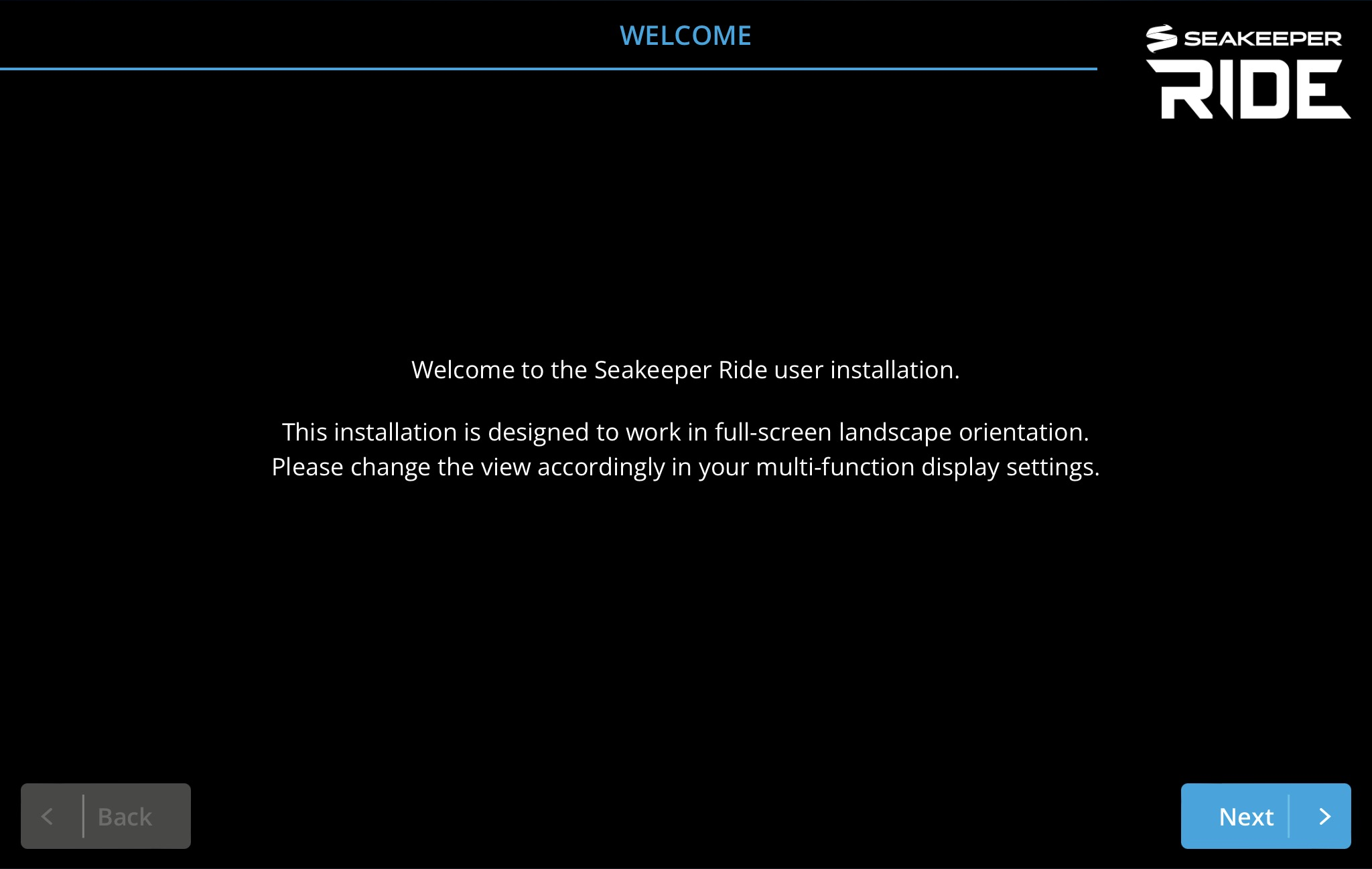
Welcome
Software Version
Install Instructions
Note: Boat must be stopped when performing install instructions.
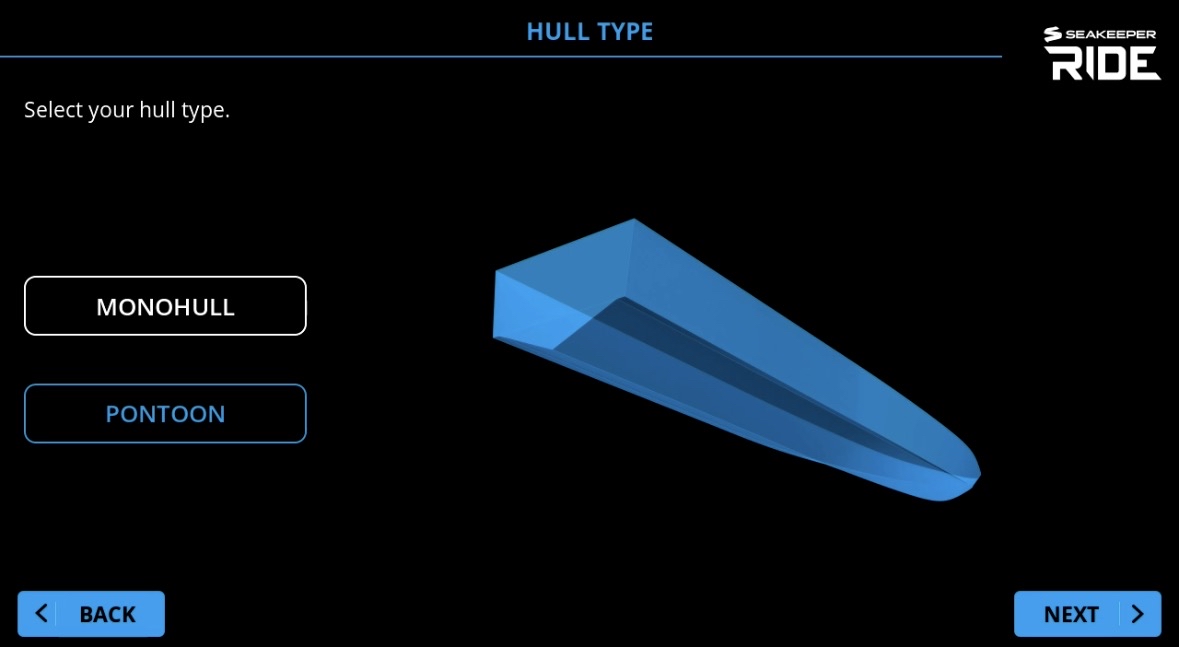
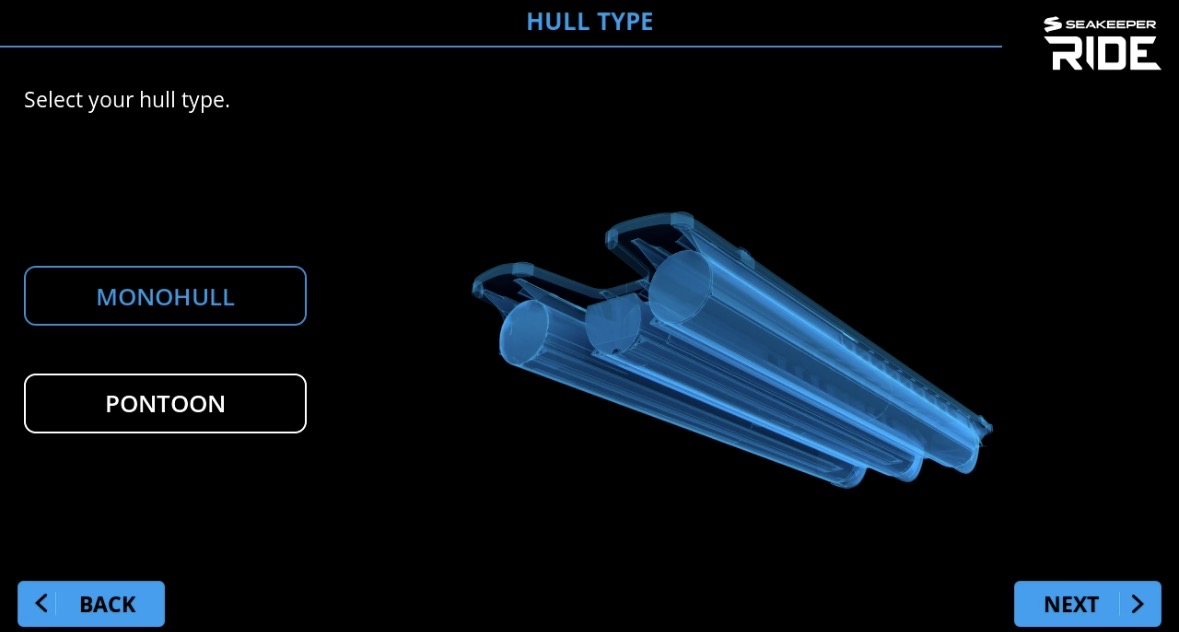
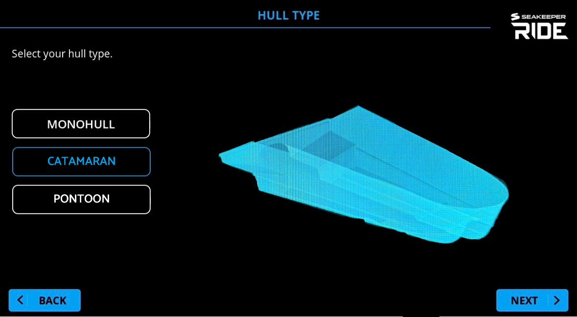
Hull Type: SMC Systems
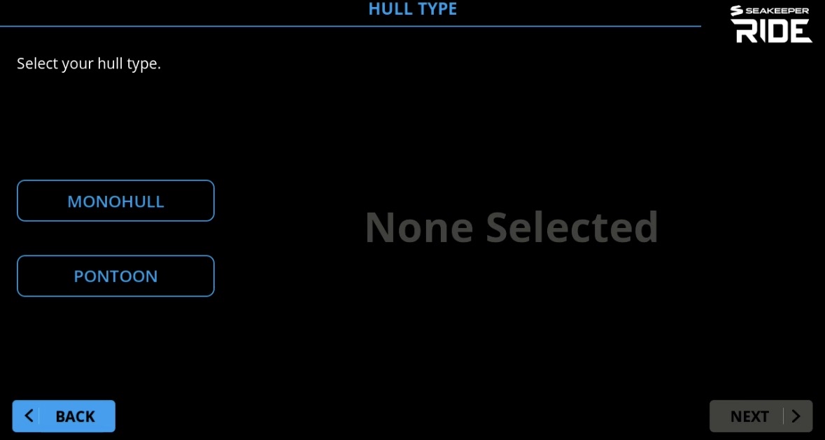
Note: Seakeeper Ride system size determines the option screen during Configuration. Seakeeper Ride 450, 525, and 600 sized systems will have the selection choices of ‘Monohull’ and ‘Pontoon.’
Hull Type: Aluminum Systems
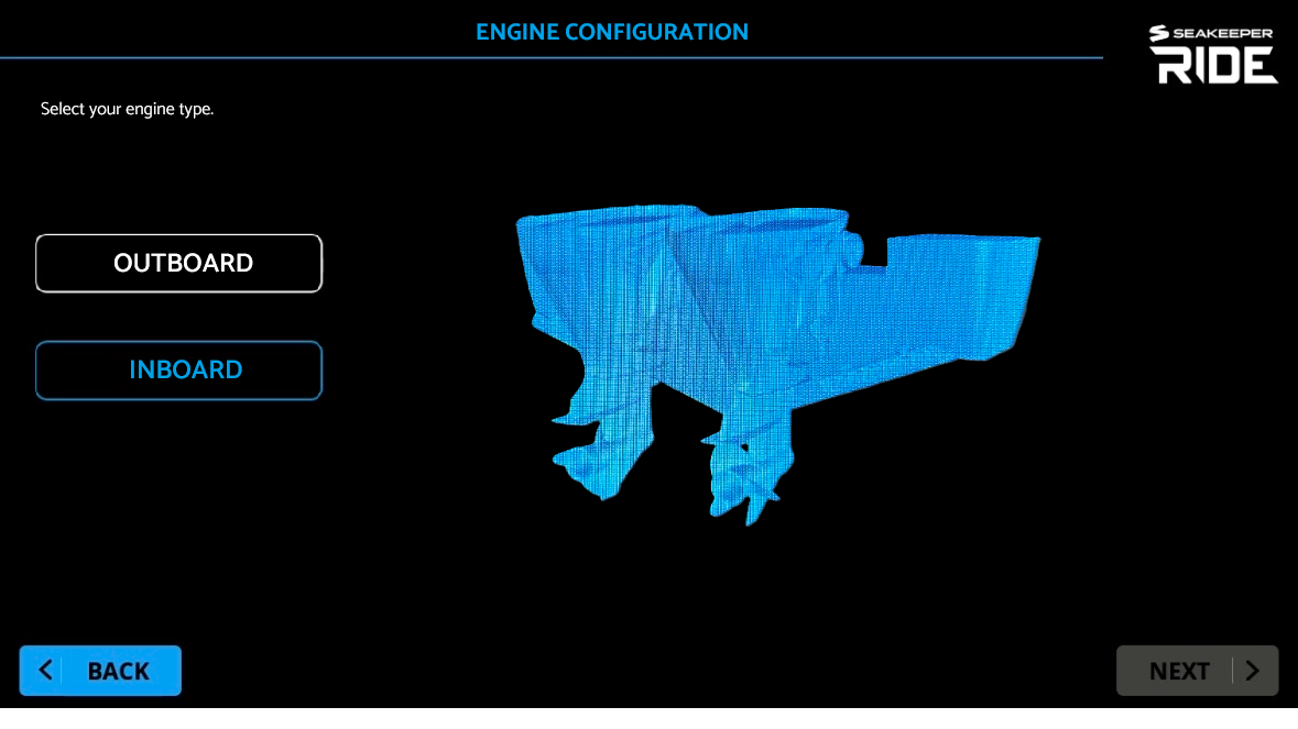
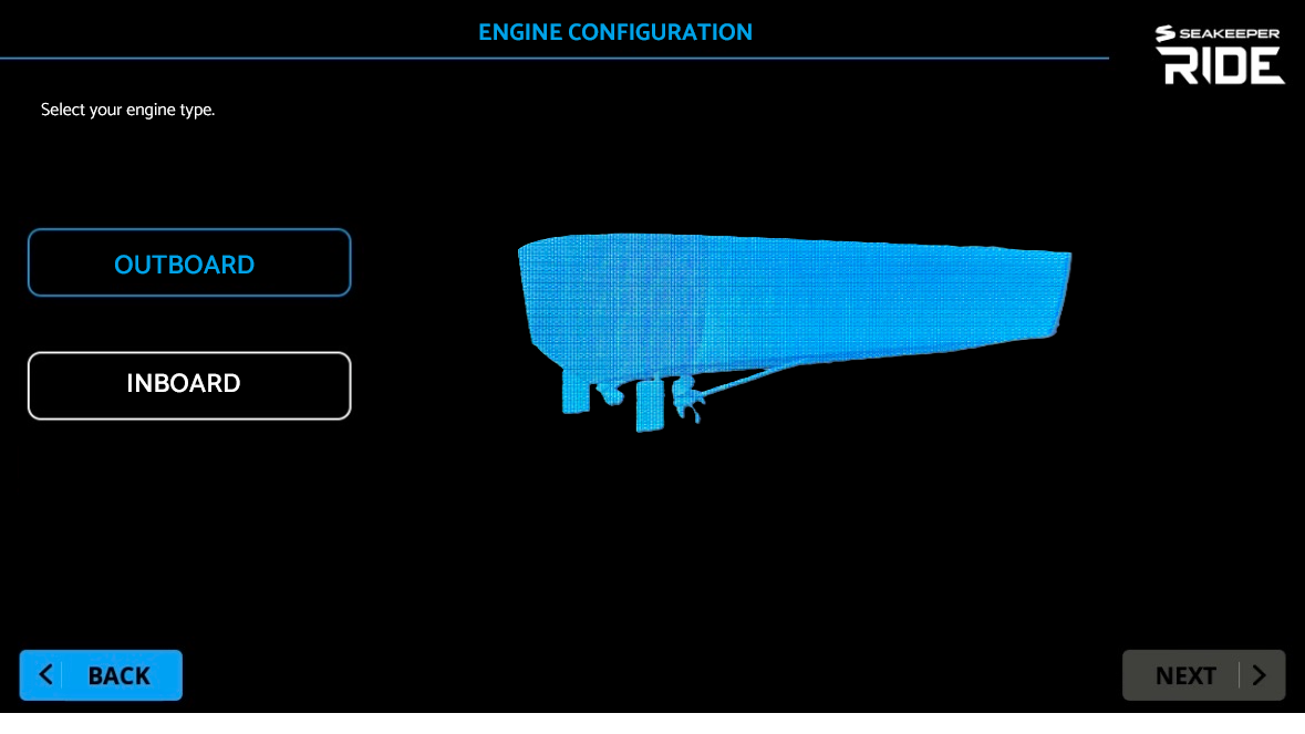
Engine Configuration: Inboard/Outboard
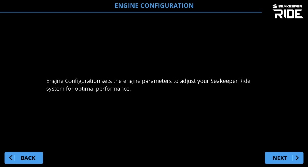
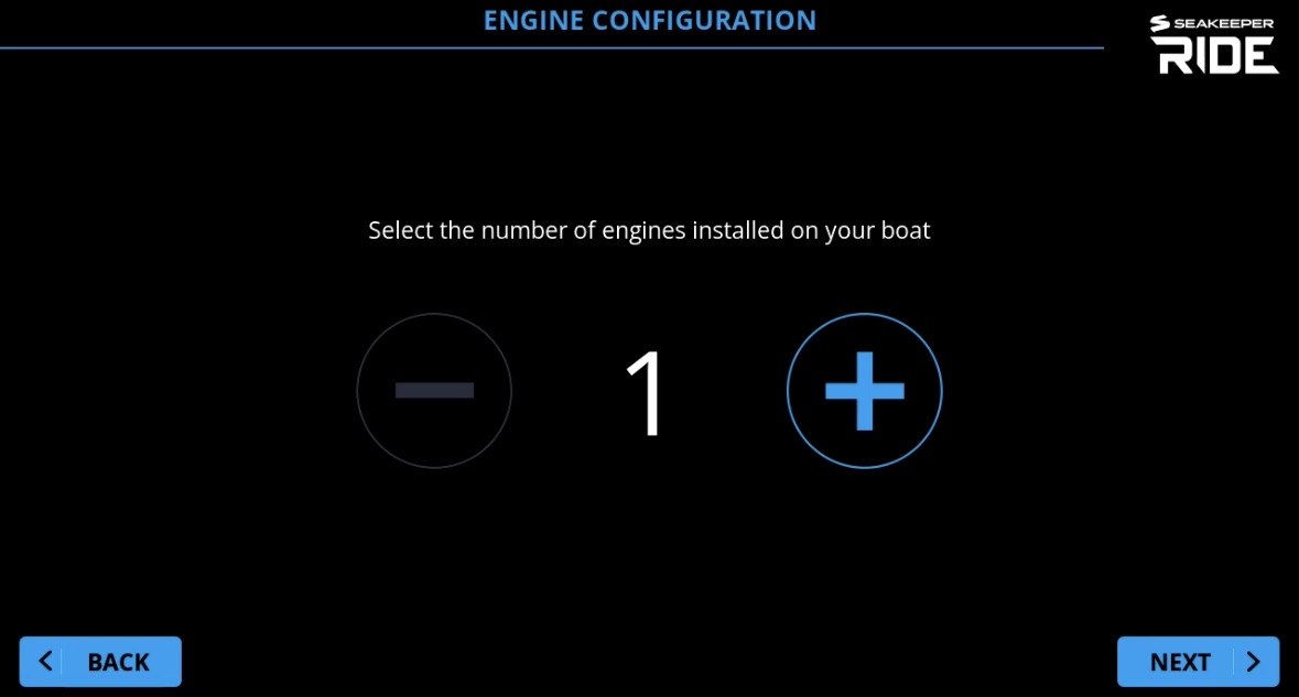
Note: Outboard and Inboard selection screens will ONLY show during the Configuration of an Aluminum Seakeeper Ride system. Example: 375A, 525A, 750 Quad, and 750-1500.
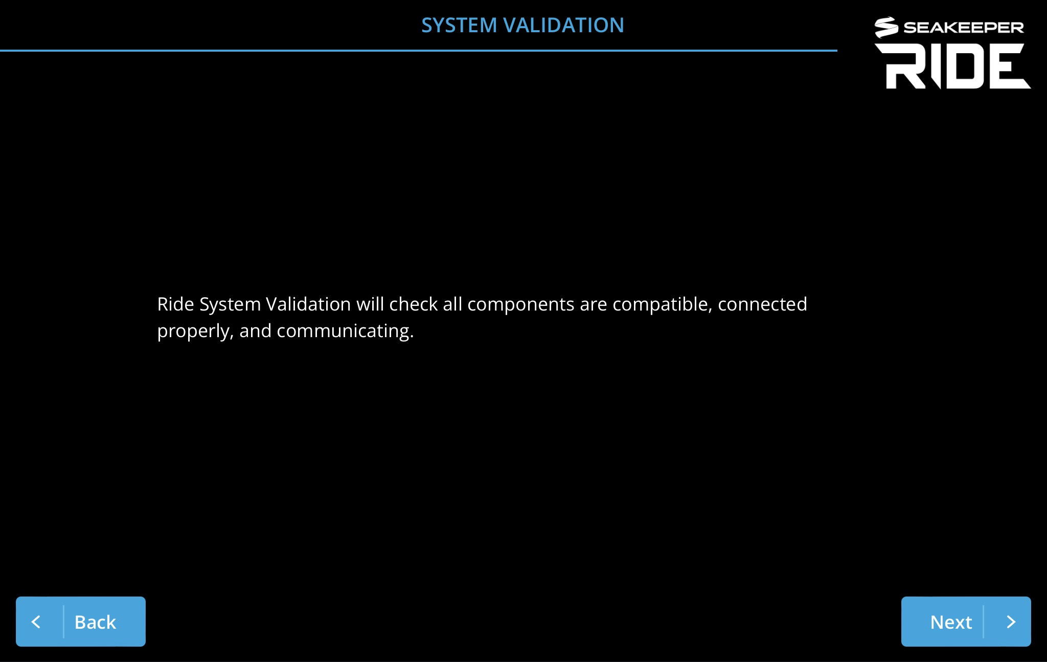
System Validation
This step ensures all components are updated to the latest software and may take a few minutes.
Software Module Orientation

WARNING: Software Module Orientation mounting position and selection is critical to safe operation of your boat. Incorrect mounting and orientation selection may result in unsafe boat handling. If you have any doubts or questions regarding this step, contact Seakeeper Ride Customer Support.
The Software Module Orientation allows the user will choose between the two possible mounting positions “STERN” or “BOW.” The Software Module senses the boats motions and is a critical piece of the installation. This selection will align the boat motion with the Seakeeper Ride components and correctly control your boat’s attitude. Visual confirmation of the Software Module’s location on board should be done at this step to ensure correct positioning on the boat.
Note: Please review the Electrical Installation Manual (Seakeeper Ride | Electrical Installation Manual) and BILT App QR code (below) for precise details on the Software Module location for best performance.

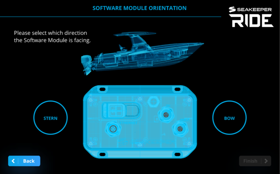
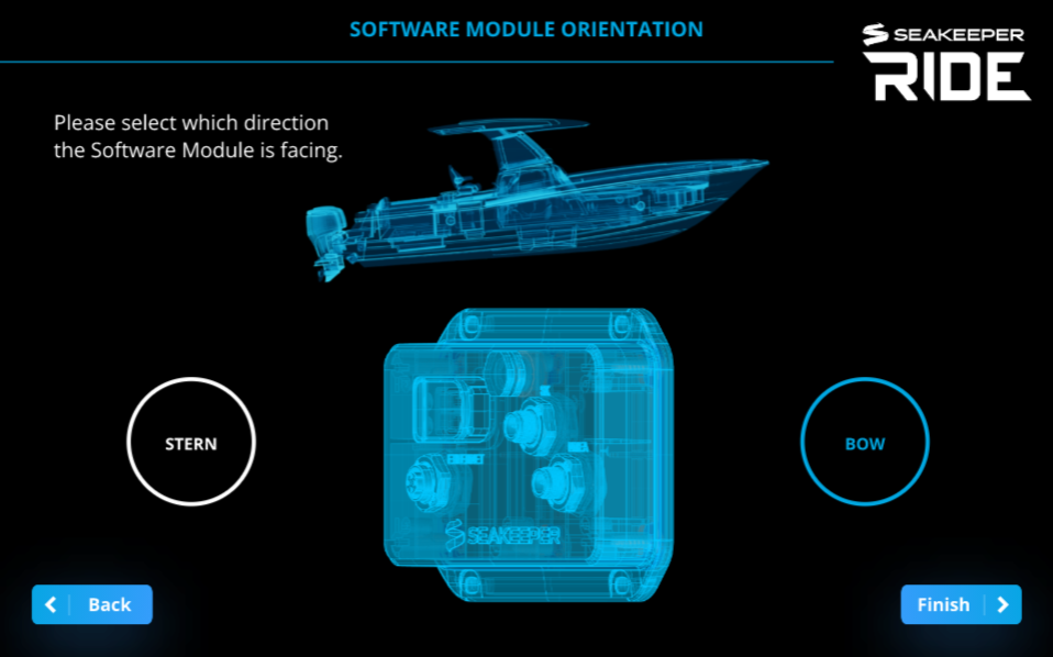
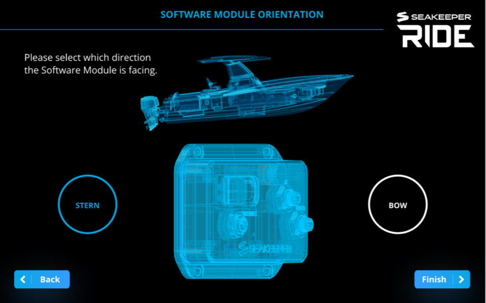
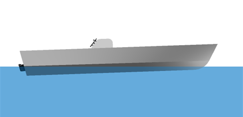
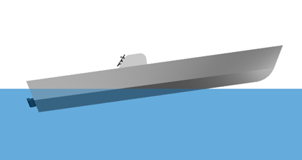
Note: If the operator is facing the Software Module and are physically facing the back of the boat, the Software Module orientation would be ‘Bow.’ If the operator is facing the Software Module and physically facing the front of the boat, the Software Module orientation would be ‘Stern.’
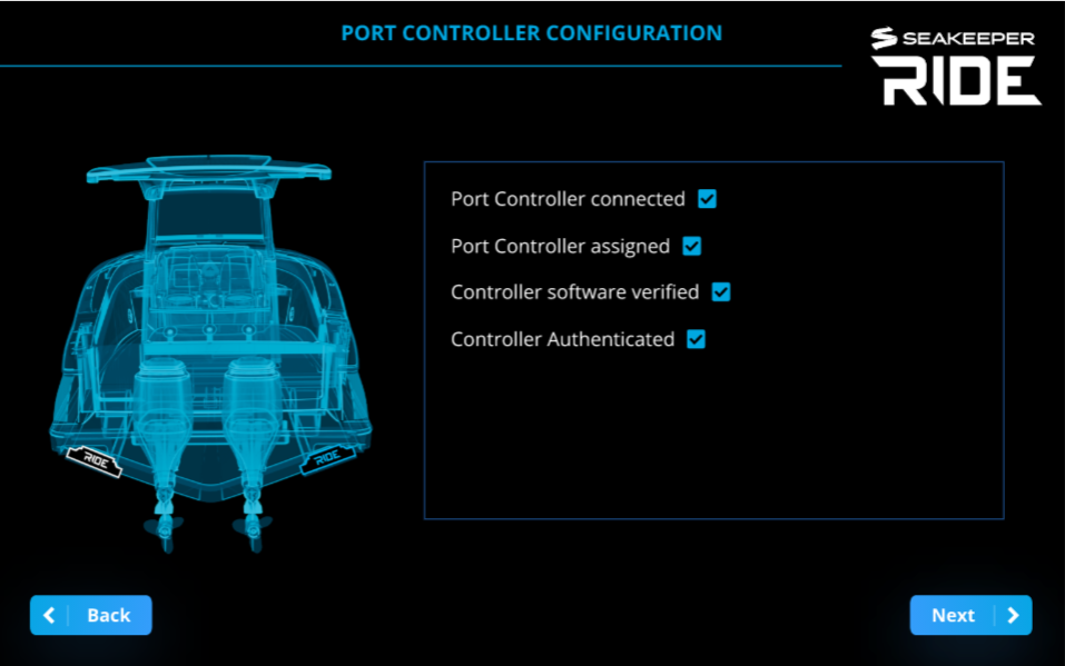
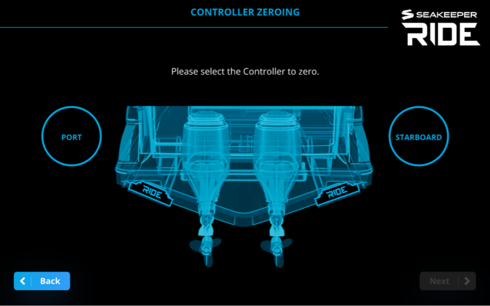
Controller Configuration
This step will assign the location, orientation and zero position for each Controller.
For Seakeeper Ride Quad systems these steps will need to be repeated for each of the four (4) Controllers. The Software Module will automatically determine the correct quantity of controllers and display information accordingly. The location of each controller to each Distribution Module is not pertinent.
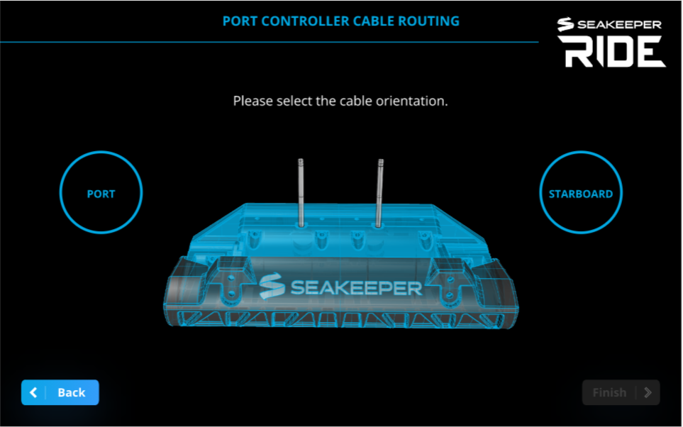
The on-screen prompts for Controller configuration will have you start with both Actuators unplugged from the Distribution Module. Plug in the Port Side Actuator cable to the Distribution Module and select the Port Controller Cable Routing.
Notes:
- Due to engineering efforts to make the Seakeeper Ride equipment more versatile for ease of installation, the Controllers must follow a Configuration procedure that tunes them for proper operation. This requires the first-time installation to determine the location of the Controller, the cable side of the Controller and the zero position of the controller. Before proceeding you will need to know which cable end belongs to which Controller (which cable end is Port side and which cable end is Starboard side). You will also need to know how the Actuator is mounted within the Controller. It can be flipped 180 degrees in order for the cable to be routed as Port or Starboard to avoid hull structure or obstacles when pulling the cable from the actuator to the Distribution Module.
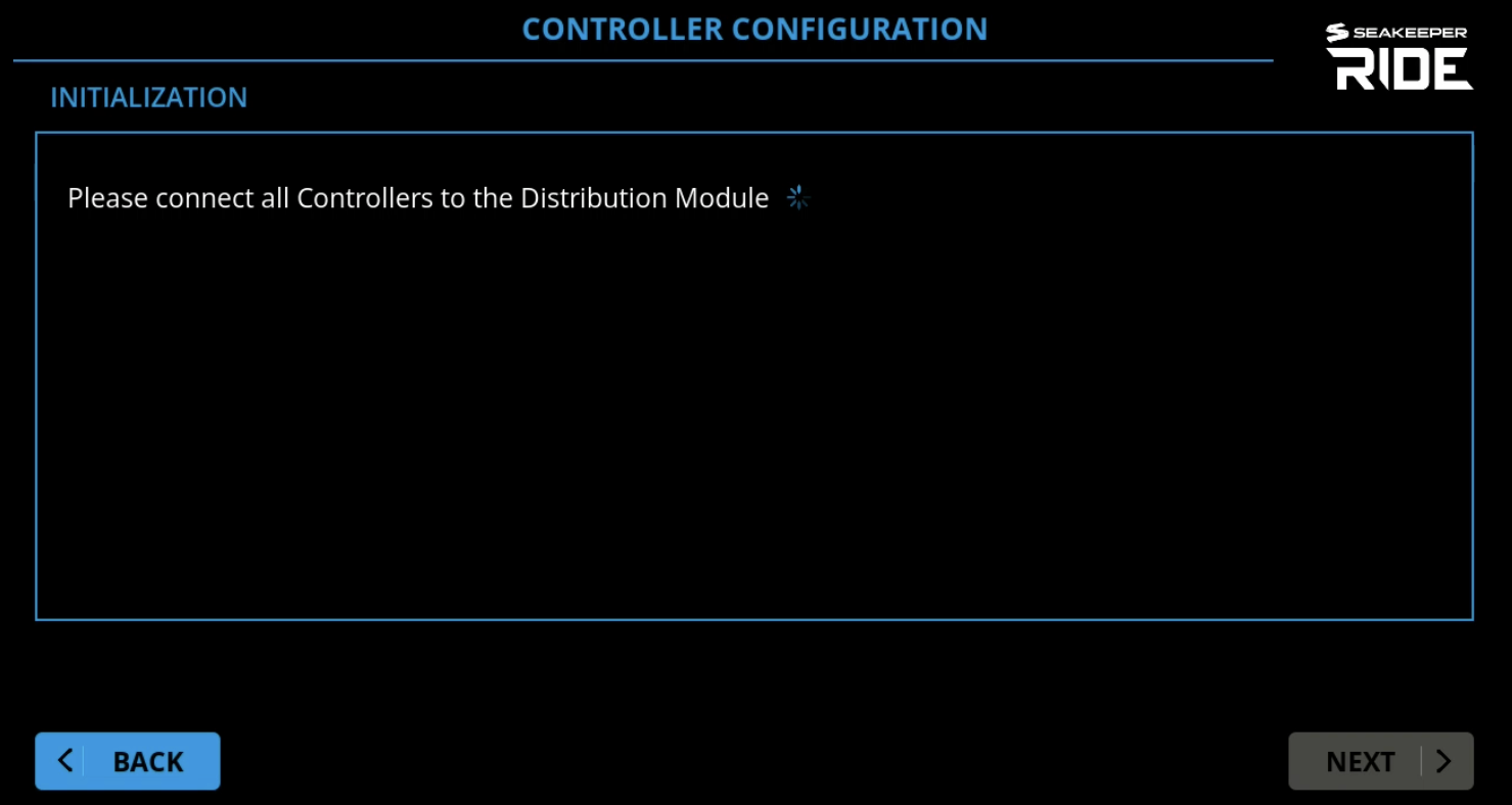
- During Controller Configuration, ‘Please Connect all Controllers to the Distribution Module’ with a blue waiting wheel may show on screen and not continue even when the Controller cables are inserted. This is sometime refered to as Stuck In Init (initialization) and has multiple potential causes. See the Stuck In Init issue in the Troubleshooting Guide.
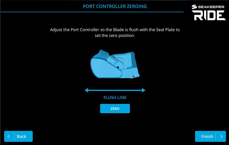
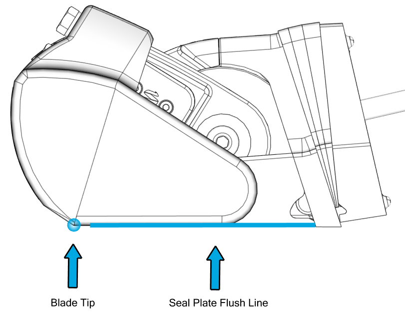
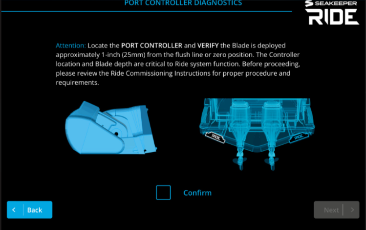
Zeroing means setting the bottom tip of the Blade flush, or in line with the Seal Plate. The Blade should not sit low where it will capture water or high which will result in diminished system response time and authority.
Plug in the Starboard Actuator so that both Cables are plugged into the Distribution Module.
Note: Follow installation wizard to configure Starboard Controller.
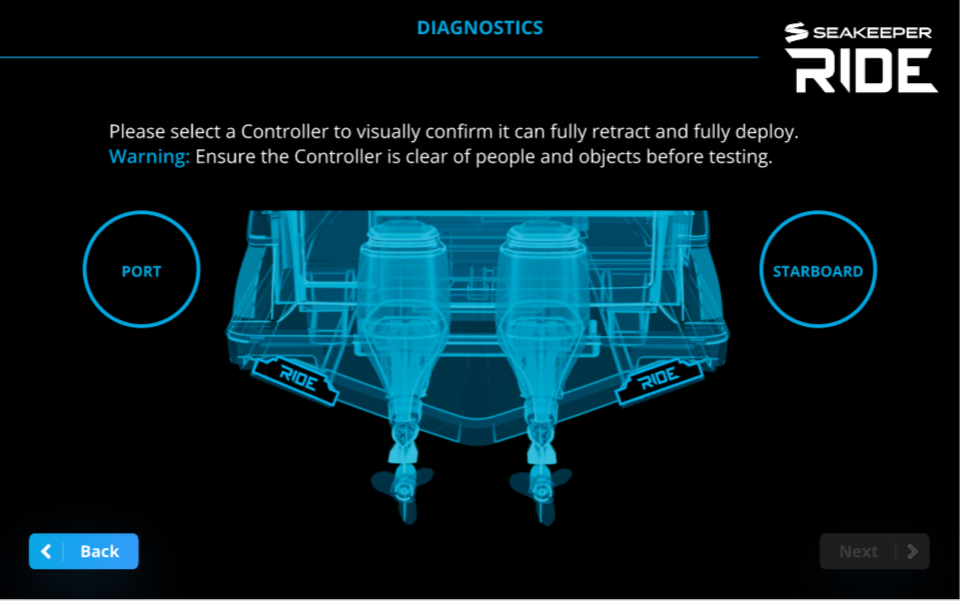
Diagnostics
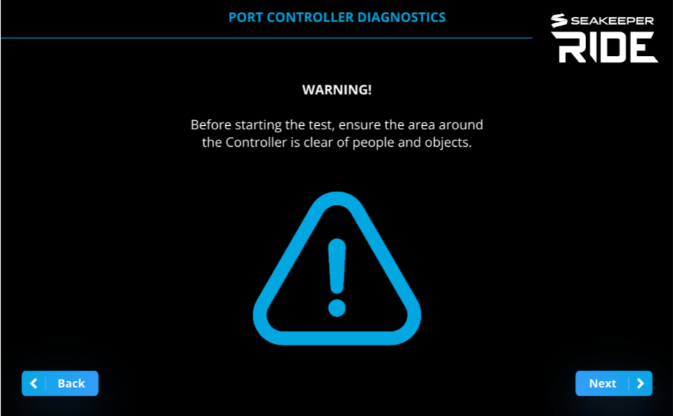
WARNING: Diagnostic’s functions do not observe vessel speed, DO NOT attempt to perform Diagnostics when vessel is moving!!
Note: Vessel must be stopped when performing Diagnostics.
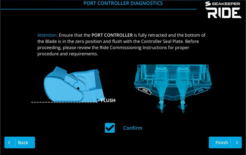
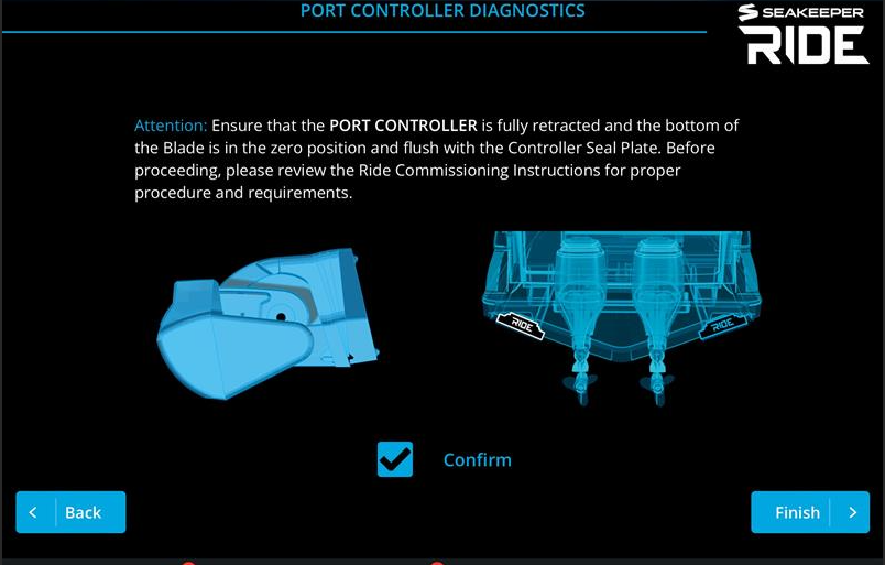
Diagnostics tests the mechanical travel, direction of motion, and communication of the Seakeeper Ride system prior to sea trialing. Please pay attention to which Controller side (Port or Starboard) you are diagnosing, so the movement of the controller matches the indicated movement on the Ride App Screen
Note: Diagnostics will be completed twice to check that both Actuators are functioning correctly. If your system has a keypad, the lights will not function during Diagnostics.
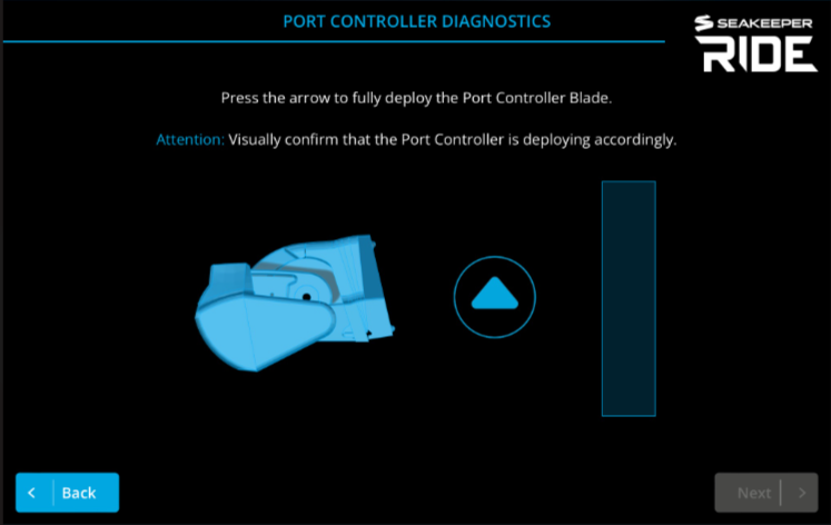
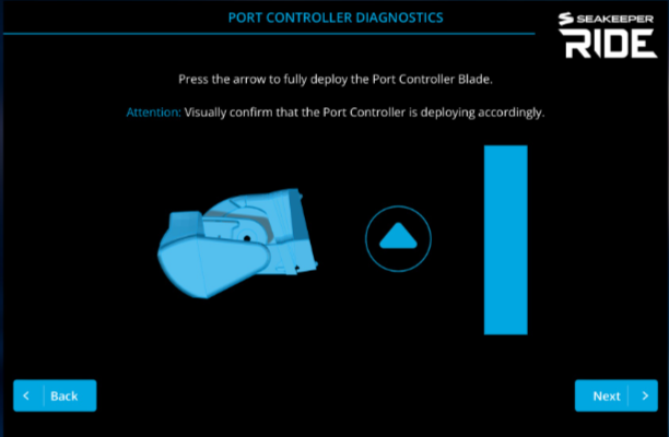
Note: In order to proceed you MUST achieve full deployment in order to select the ‘Next’ button.
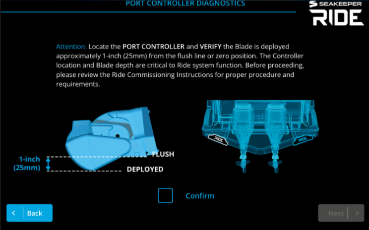
Note: In order to proceed you MUST retract deployment to Zero position in order to select the ‘Next’ button.
The following screen informs the users about TCC (Trim Command Curve) and where to locate it when setting changes are needed.
Note: Refer to the TCC (Trim Command Curve) instructions here – 3.3. Trim Command Curve (TCC).
You have now fully Configured the Seakeeper Ride system, and it is ready for the water!

Note: The speed of the boat, GPS connection, and the system being in Auto or Manual mode will all influence how Seakeeper Ride behaves. Even if Seakeeper Ride is set up correctly, the Controllers may have limited range based on these factors. See the Seakeeper Ride Operation Manual 2.1. Home | Auto Mode and 2.2. Home | Manual Mode for Home Screen controls.
If the Seakeeper Ride system has already been configured previously, then please refer to the table on the following page for expected bahavior and see 2.6. Service – Seakeeper Manuals for information on the Service Menu Items.
4. Service Menu Items
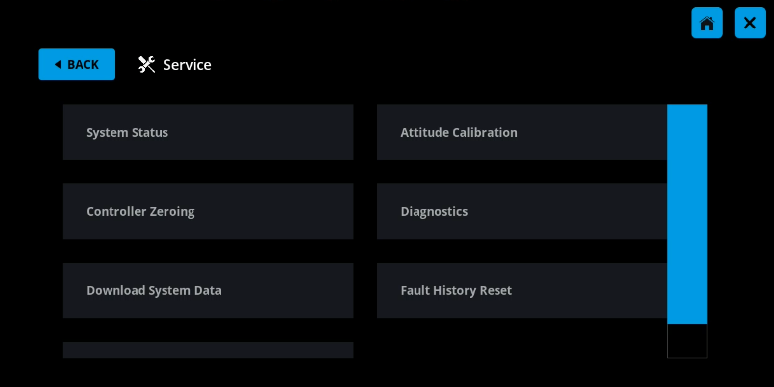
The Service Menu items can be utilized for adjusting certain parameters of your Seakeeper Ride system. Attitude Calibration and Controller Zeroing can be done without a Factory Reset. Changing Software Module Orientation, Controller Assignment, and Controller Orientation (cable routing side) requires a Factory Reset.
From the Seakeeper Ride Home Screen, press the Menu button and then press Service.
See 2.6. Service – Seakeeper Manuals for details on all Service Menu items.
5. Testing the System
Once the system has been configured, test that the system is operating correctly. While testing the system, make sure the boat is stationary and has GPS connection. Testing is best done with the boat out of the water, allowing the Controllers to be seen more clearly. If the Seakeeper Ride system does not perform as indicated in any of these steps, return to the previous sections and repeat the associated procedures as necessary.
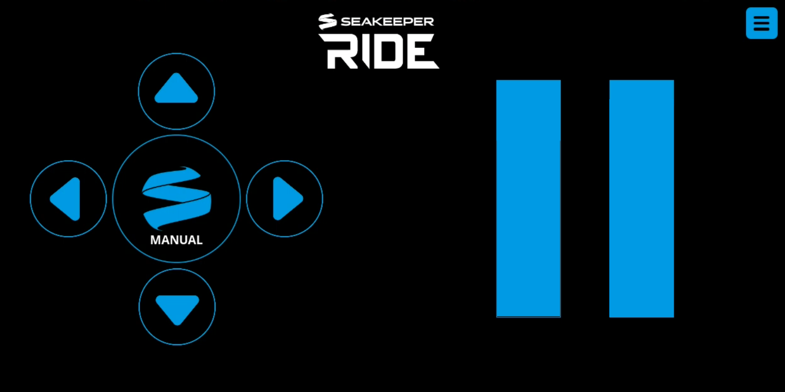
Note: Pressing the left and right directional arrows move the Blade, blue fill bar, and Keypad lights on the opposite side. For example, pressing the left, or port side, arrow will change the starboard side blue fill bar.
- Enter Manual Mode by pressing the Seakeeper Logo in the center of the directional arrows on the Home Screen of the display or the Keypad.
- Look over the transom of the boat to visually confirm the Controller’s Blades are fully retracted and flush with the Seal Plate.
- Use the up directional arrow to fully deploy the Blades. The blue bars on the screen should be filled in with blue completely. Look over the transom of the boat to verify the Controller Blades have deployed completely.
- Use the down directional arrow to retract the Blades completely.
- Press the right directional arrow until the port side blue bar fills in completely.
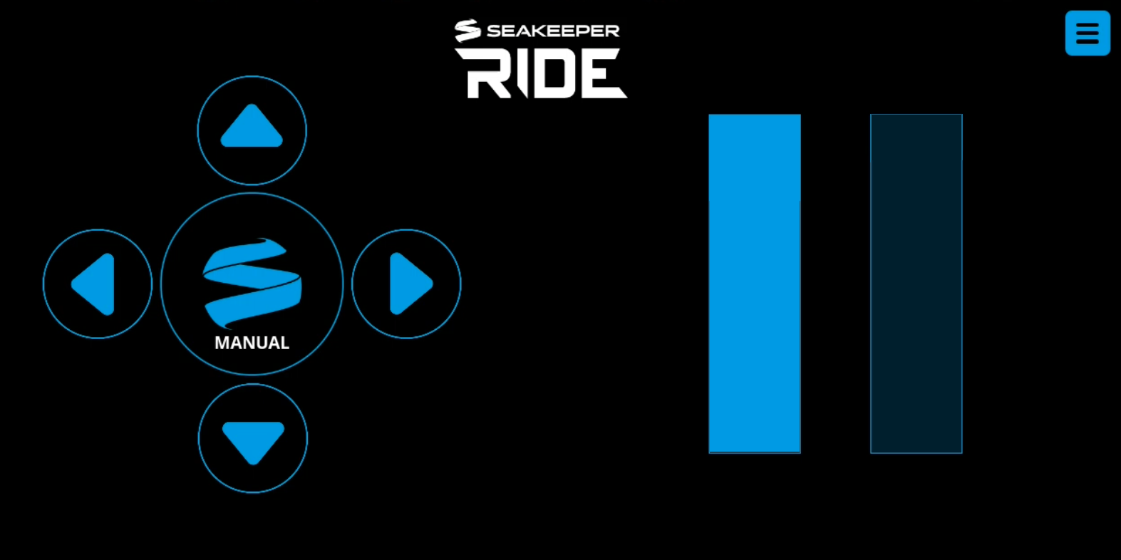
- Visually confirm that the port Controller’s Blade is deployed completely.
- Repeat steps 5-6 for the left directional arrow corresponding to the starboard Controller.
The Seakeeper Ride system configuration is now complete. Please refer to the Quick Start Guide to begin using the Seakeeper Ride system.
Note: The speed of the boat, GPS connection, and the system being in Auto or Manual mode will all influence how Seakeeper Ride behaves. Even if Seakeeper Ride is set up correctly, the Controllers may have limited range based on these factors. Refer to the table below for more information, and see the Seakeeper Ride Operation Manual 2.1. Home | Auto Mode and 2.2. Home | Manual Mode for home screen controls.
| Auto Mode | Manual Mode | |
|---|---|---|
| Speed (with GPS signal) | ||
| 0-10 mph | Blades can be moved fully together by trimming with the up and down directional arrows. The left and right directional arrows will apply a trim to the system but will not cause the Blades to move at these speeds. The Blades will not move automatically. | Blades can be moved fully with the directional arrows. |
| 10+ mph | Blades will deploy automatically based on movement of the boat and the TCC. At higher speeds, the Blades will deploy less. Blades can also be manually trimmed with the directional arrows. | Blades can be moved fully at lower speeds and will allow less movement at higher speeds. |
| GPS | ||
| Connected, Good Signal | Blades will deploy as described above in the ‘Speed’ section. | Blades can be moved to the maximum range allowed by the speed. |
| No Signal | Auto Mode will be disabled. Fault will be shown on screen. | Blades can be moved with the directional arrows up to 25% deployment regardless of speed. |
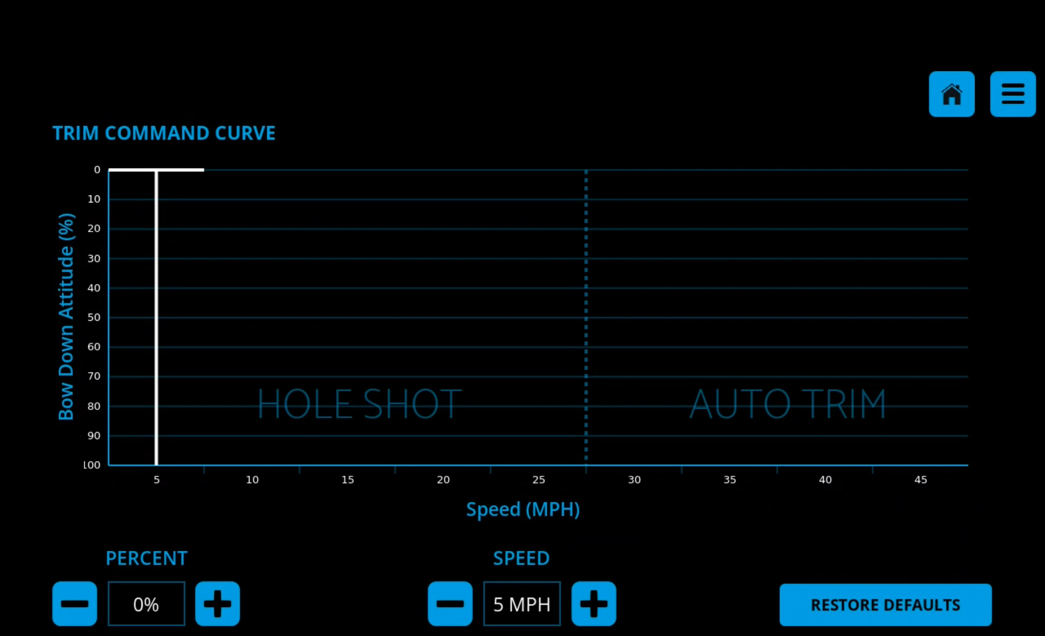
6. Trim Command Curve (TCC)
The Trim Command Curve (TCC) allows the operator to set a preferred trim at speeds of 5-45 mph in 5 mph increments. This important feature allows the boat to get on plane significantly faster by deploying the Blades when accelerating. The TCC additionally allows the operator to adjust the attitude of the bow by setting preferred Blade deployment at cruise speeds.
The TCC is split into two distinct zones, one for Hole Shot (from 5-25 mph) and one for Cruise (30-45 mph).
The Hole Shot from 5-25 mph is utilized strictly when the boat is accelerating, to bring the bow down and maintain a view of the horizon. This feature does not function when decelerating, preventing stuffing the bow of the boat. To re-engage, the boat must slow below 5 mph before accelerating again.
The Cruise portion of the Trim Command Curve is active from 30-45 mph providing additional bow down attitude as preset by the operator if the boat is accelerating, maintaining speed, or slowing down. Only customize the Trim Command Curve in this speed range after attempting to trim the boat using the motor trim and distributing the weight of passengers and other loads evenly on the boat.
Notes on the TCC:
Note: The trim of boats with adjustable propulsion like outboard motors, stern drives and surface drives is largely dependent on the trim of the propulsor. Please familiarize yourself with proper operation of the propulsion trim before adjusting the TCC. For boats with 3 or more engines, where Seakeeper Ride is mounted forward of the propellers, we recommend reducing TCC to 0 for all speeds and then working to increase TCC as desired.
The TCC will be preset. To customize the TCC:
- Follow the steps to turn on the system in Section 3.1.
- Ensure the boat is in neutral in safe waters with no obstructions or boat traffic.
- With the Seakeeper Ride system turned on, select the Menu button
 on the MFD.
 - Select ‘Settings’ then ‘Trim Command Curve.’
- The display shows speed at the bottom (x-axis) and percent on the left (y-axis).
- Select the speed segment by clicking on the specific speed column. Each speed segment is 5 mph. Speed segments start at 5 mph and go to 45 mph. The advanced software will smoothly transition through each speed trim for seamless operation.
- By selecting the percent buttons on the bottom, add or subtract the trim command at that given speed segment.

The trim command is shown as blue fill in each column. More trim command results in more bow down influence on the boat by the Controllers. Less trim command results in less bow down influence on the boat.
- Perform a test of the selected settings by maneuvering the boat into calm open water. Once clear, accelerate the boat through the full range of speeds and monitor how the trim of the boat behaves at each speed.
- Further adjustments can be made by repeating steps 1 through 9.
7. Troubleshooting
If Seakeeper Ride does not operate correctly when testing the system in Section 5 or if the configuration process is unable to be completed because of a persisting issue, refer to the Seakeeper Ride Troubleshooting Guide for help. Reviewing and correctly following one or more of the previous configuration sections will often resolve the issue. However, there may be issues resulting from an incorrect electrical installation, which could include, a loose wire, incorrect wiring, missing components, etc. Visit the tables in the Seakeeper Ride Troubleshooting Guide to help identify possible causes of the issue and find the solution.