Seakeeper 40 Installation Manual (90715-5) 40-263-0287 to current
3.0 Electrical Installation
3.1 Electrical Installation Introduction
This section for electrical installation explains how to mount the electrical equipment and how to connect the electrical cables (Figure 16).
Reference Documents & Drawings:
- 90710– Seakeeper 40 Cable Block Diagram
- 90716 – Seakeeper 40 Operation Manual
- TB-90896 – ConnectBox Installation Guide
- Seakeeper Compatibility Technical Bulletins
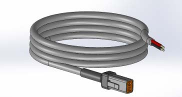
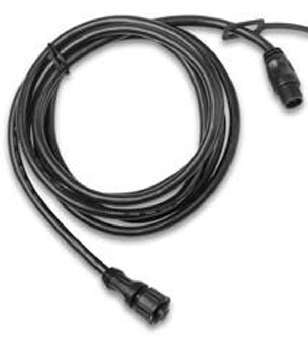
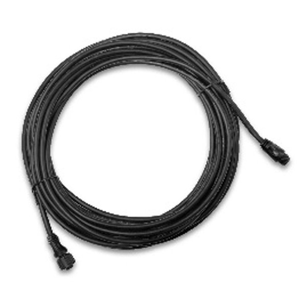
Pump Out, 16.4 ft (5 m)
Figure 16– Electrical Equipment for Seakeeper 40
3.2 Electrical Equipment Power Connections
230 VAC Power Source Requirements
- 230 VAC (nominal), 1 Phase, 50/60 Hz, 30 A
- With installations of more than one Seakeeper, a dedicated circuit breaker should be used for each Seakeeper Motor Drive Box.
Drive Box AC Power Input Connection Instructions
- AC Power Input Cable: 3 x 10 AWG (3 x 6 mm2 CSA), 10 ft (3 m) length, (P/N 20542) Seakeeper-supplied and pre-installed in Motor Drive Box.
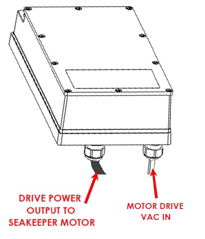
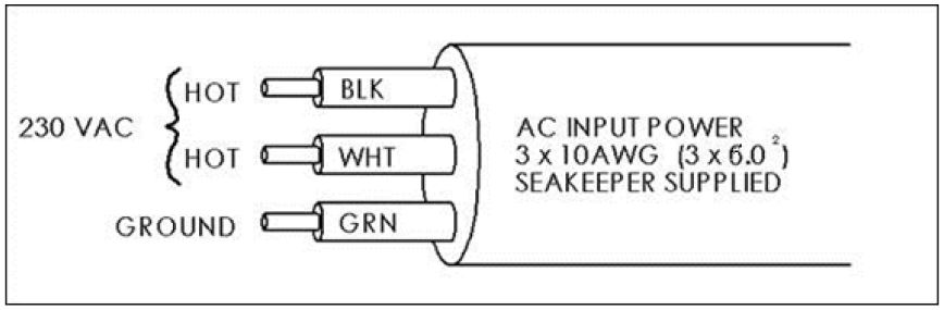
- For Seakeeper 40, connect 230 VAC wires in AC Input Cable to a 30 A, double-pole Circuit Breaker at an AC power distribution panel according to Figure 18 above.
24 VDC Power Input
- One 24 VDC, 15 A (Customer supplied breaker) for Seakeeper Control Power, AND
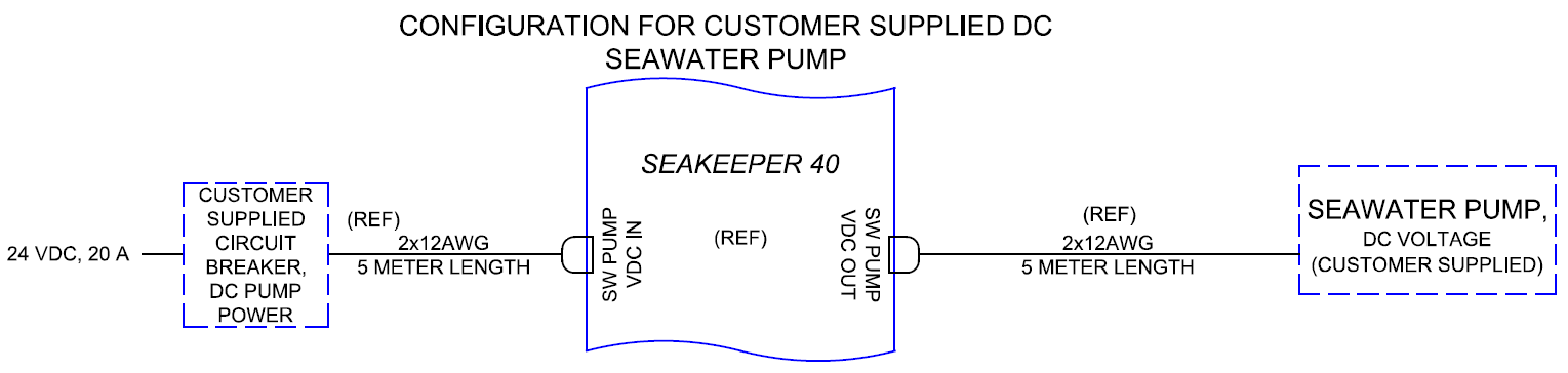
- One 24 VDC, 20 A (Customer supplied breaker) for DC Seawater Pump.
- A dedicated breaker breaker should be used for each Seakeeper control power and DC Seawater Pump source.
DC Power Connection Instructions

Reversing polarity on the DC power input to the Seakeeper can result in damaging the electronics in the control system.
- 24 VDC, 2 x 12 AWG (3 x 4 mm2 CSA) Seakeeper supplied.
- Install Seakeeper provided DC Power Input Cable (P/N 20248),
as shown in Drawing No. 90710 – Seakeeper 40 Cable Block Diagram.
- Route DC Power Input Cable to DC Power Distribution Panel.
- Terminate positive (B+, Red) conductor through dedicated over-current protection device (customer supplied) and a dedicated Seakeeper isolation switch (customer supplied) then directly to battery plus terminal.
- Terminate negative (B-, Black) conductor directly to battery negative terminal or negative bus.
- Before connecting DC Input Cable to Seakeeper, check for proper voltage and polarity with a DC multimeter using Figure 19 below.
- Connect DC Input Cable to 24 VDC input receptacle on Seakeeper.
- Install Seakeeper provided DC Power Input Cable (P/N 20248),
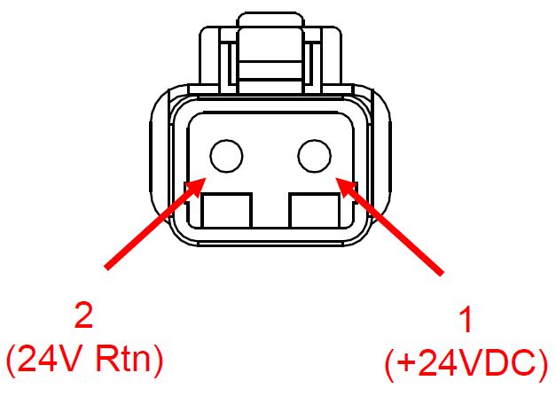
When energizing DC power for the first time, if ConnectBox does not power up immediately then disconnect and inspect connector polarity.
DC Seawater Pump 24 VDC Power Input Connection Instructions

Connecting the DC Seawater Pump in any other manner than recommended by Seakeeper may cause internal failure.
- Install Seawater Pump Input Cable (P/N 20248) to overcurrent protection corresponding to Seawater Pump selected as follows:
- Connect the 12 AWG positive conductor (Red) through dedicated overcurrent protection device (Customer supplied), maximum of 20 A, to dedicated battery isolation switch.
- Connect 12 AWG negative conductor (Black) directly to battery negative terminal or DC main negative bus bar.
- Before connecting Seawater Pump Input Cable to Seakeeper, check for proper voltage and polarity with a DC multimeter using Figure 20 below.
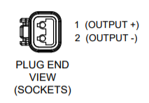
- Connect Seawater Pump Input Cable to “SW Pump 24 VDC In” connector on the Seakeeper.
DC Seawater Pump 24 VDC Power Output Connection Instructions
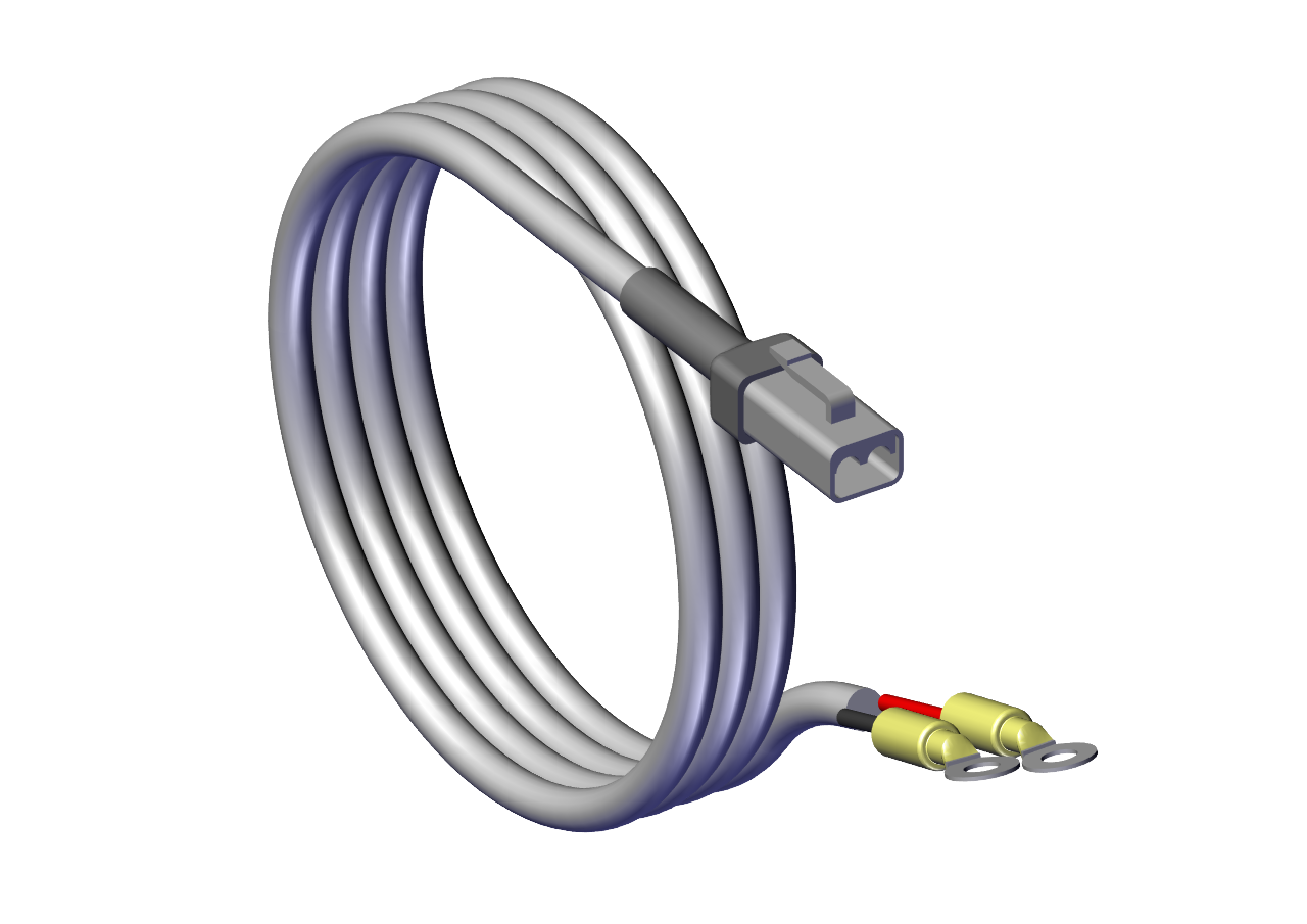
- Connect Seawater Pump Output Cable (P/N 20594) to the Seakeeper 40 “SW Pump 24 VDC Out” for DC power output to the Seawater Pump.
- Seawater Pump Output Cable is a 2 x 12 AWG cable, 16.4 ft (5 m) length, with a male Deutsch connector on one end and two terminal ring lugs on the pump end (Figure 21).

- Seawater Pump Output Cable must be routed and installed in the vessel from the Seakeeper 40 “SW Pump 24 VDC Out” Deutsch connector to the DC Seawater Pump cable. See Figure 22 for the block diagram.
3.3 Electrical Equipment Ground Connections
Seakeeper to Vessel Ground Connection Instructions
- Connect the Seakeeper foundation to vessel ground.
- Install Ground Cable (10 AWG or 6.0 mm2, Customer supplied) from the M6 brass ground stud on the Seakeeper rear foundation (Figure 23) to a suitable vessel ground. The ground cable should be installed on the inside rear of the foundation as shown below. If possible, install ground cable prior to installing the Seakeeper into the vessel. If there is no access to the ground stud from below the rear of the Seakeeper once installed, the rear cover, upper rear cover, and GCM bracket will need to be removed to access the ground stud from above the Seakeeper.

NOTE: USE ONLY THIS LOCATION FOR GROUNDING THE SEAKEEPER TO THE VESSEL GROUND.
2. Install Ground Cable (10 AWG or 6.0 mm2, Customer-supplied) from the M6 brass ground stud on the
Seakeeper rear brace to a suitable vessel ground.
- EN/IEC 60204-1:2016, Clauses 6.3.3 and 8.2.3
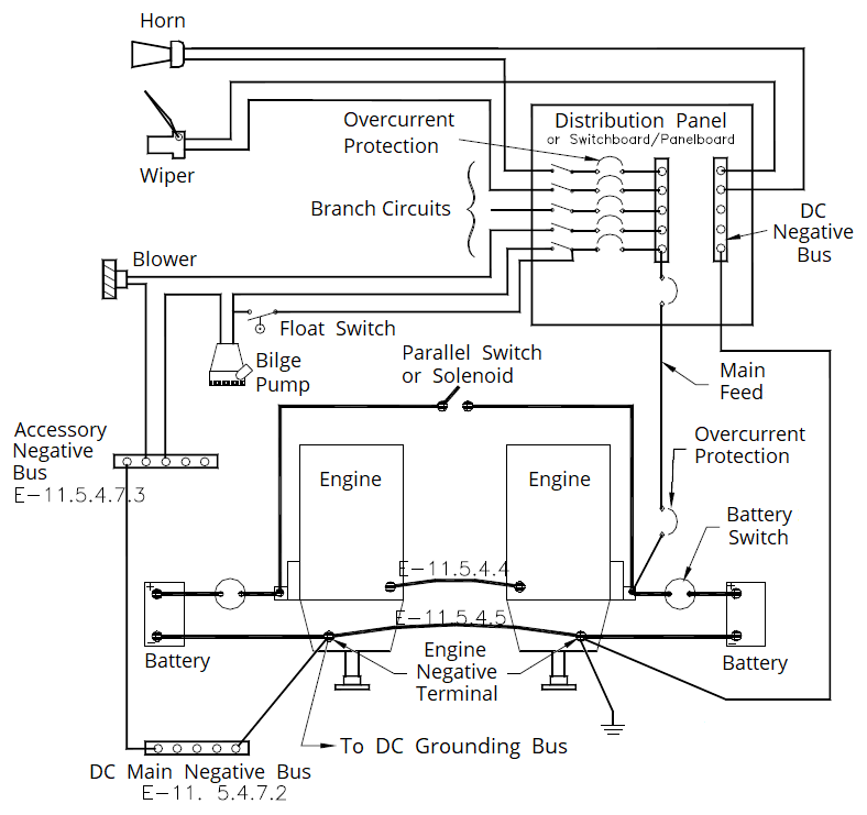
- ABYC E-11 July 2021, Clauses 11.5.2 and 11.17
3. Ground connection should be made with vessel bonding system, if available. However, the ground is not
referring specifically to a bonding system but for outboard boats generally refers to the outboard engine
negative terminal. Per ABYC E-11 (2018), Clause 11.5.2.7.4: If the negative side of the DC system is to be
connected to the ground, the connection shall be made only from the engine negative terminal, or its bus,
to the DC grounding bus. This connection shall be used only as a means of maintaining the negative side of
the circuit at ground potential and is not to carry current under normal operating conditions.
4. A proper ground connection is critically important for corrosion protection and helps to ensure the
ignition protection of the unit by ensuring it does not carry any stray current.
ABYC E-11, figure 4A
3.4 ConnectBox Connections
A display is required with the installation of a Seakeeper 40 to support the full functionality of the unit through the Seakeeper App in addition to the ConnectBox. The Seakeeper App provides an interface for controlling the Seakeeper or viewing the Settings, Service, Info, and Alarm pages. The Seakeeper ConnectBox can be helm-mounted to provide an additional interface for the control of the Seakeeper but does not replace the need for a Seakeeper compatible display.
The Seakeeper 40 must be connected to a compatible Multi-Function Display (MFD) for operation.
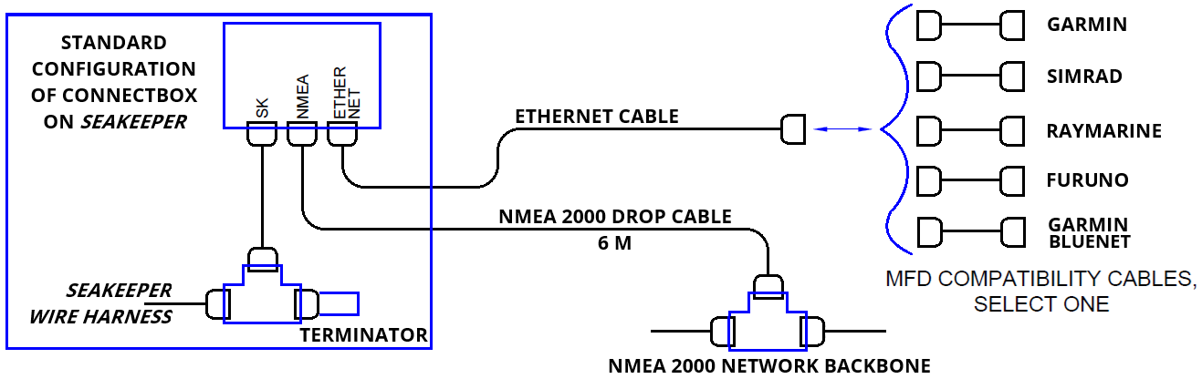
The following figure provides a schematic of the display. The subsequent sections outline the instructions and references for connecting the Seakeeper 40.
Reference Drawing
Connecting to a Compatible MFD
- The Seakeeper 40 can be connected to a variety of available MFD systems. Refer to the Technical Bulletins Section of the Seakeeper Technical Library for manufacturer specific MFD compatibility technical bulletins.
- MFD specific Technical Bulletins will be updated regularly as new MFD systems become compatible. Currently GARMIN, RAYMARINE, NAVICO (Simrad, Lowrance, B&G), FURUNO, and GARMIN BLUENET offer compatible MFD models.
- Once a compatible MFD has been selected, refer to the appropriate manufacturer specific compatibility Technical Bulletin listed above for integration instructions.
- Connect Seakeeper-supplied M12 D-Code, 82 ft (25 m), cable (P/N 30355) to MFD manufacturer-specific Ethernet adapter cable. Custom Ethernet cables for specific MFD manufacturers are available through Seakeeper and must be purchased with the Seakeeper 40 when connecting to an MFD.
NMEA 2000 Network Connection
The Seakeeper 40 requires a connection to the vessel’s NMEA 2000 network backbone via a drop cable for access to the GPS signal. The Seakeeper 40 will monitor information on the NMEA network to support and optimize the performance of the Seakeeper 40. If no GPS signal is detected, a warning will appear on the Seakeeper display. The Seakeeper will not spool-down, but the operation of the unit will be limited until the GPS signal returns. Refer to TB-90896 – ConnectBox Installation Guide for details of installation.
- Install customer-supplied NMEA 2000 Tee Adapter (space required: approximately 4 W X 3 H in. (102 X 76 mm).
- Connect NMEA Backbone to Tee Adapter.
NOTE: NMEA drop cable can be no longer than 19.6 ft (6 m) in length.
- ConnectBox can be remote mounted at a location closer to the NMEA backbone when the 6 m drop cable length is insufficient. See ConnectBox Helm Mounting instructions below.
- If the 6 m drop cable is insufficient in length, extend the NMEA 2000 backbone towards the ConnectBox.
- Connect Seakeeper-supplied NMEA cable (P/N: 30332) to the customer-supplied NMEA 2000 Tee Adapter on vessel’s NMEA 2000 backbone.
- An active NMEA 2000 compatible GPS signal is required on the vessel’s NMEA 2000 backbone to operate the Seakeeper 40.
- If no GPS signal is detected, a Speed Over Ground (SOG signal) warning will be present on the Seakeeper app. See TB-90640 for NMEA connectivity guidance.
- An active NMEA 2000 compatible GPS signal is required on the vessel’s NMEA 2000 backbone to operate the Seakeeper 40.
ConnectBox Helm Mounting – Optional
- Console space required: Approx. 3.41 L x 4.15 W in. (87 x 106 mm).
- Mounting Instructions, Surface Mount: See Drawing No. 90558 – Seakeeper ConnectBox Helm Mounting Kit, for details. Seakeeper ConnectBox 3D Model available upon request.
- Mount ConnectBox Replacement Blank insert into Seakeeper 40 top cover at the original location of the ConnectBox.