Seakeeper 18 Operation Manual (90673-2); S/N 18-234-2475 to Current
7.0 Specifications and Summary
All Seakeeper 18 specifications can be viewed here (seakeeper.com).
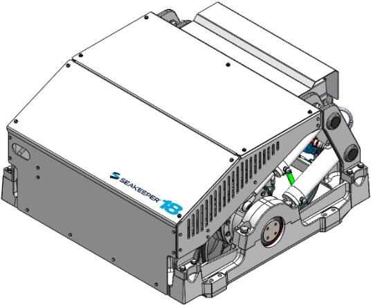
Arrangement
The Seakeeper 18 consists of the Flywheel, Enclosure, Foundation, Electronics, Brake, Cooling, and Cover Subsystems.
Installation Location
The Seakeeper is a torque device and does not have to be installed in a specific hull location or on the vessel’s centerline. However, the Seakeeper should not be installed forward of amidships to minimize high acceleration loading due to hull-to-wave impacts during operation at high speed or in large waves. Contact Seakeeper if a forward installation location is being considered.
Mounting Dimensions
See Drawing No. 90544 – Seakeeper 18 Bolt-In Installation Details.
See Drawing No. 90545 – Seakeeper 18 Bond-In Installation Details.
Loads
The installer is responsible for designing the foundation to which the Seakeeper is attached and for ensuring that this foundation can safely transfer the concentrated Seakeeper loads from the frame to the adjacent hull structure. Loads that the Seakeeper imposes on the hull structure are explained on Drawing No. 90544 – Seakeeper 18 Bolt-In Installation Details and Drawing No. 90545 – Seakeeper 18 Bond-In Installation Details; these loads do NOT include vessel motion accelerations, such as vertical slam loads which can be significant for higher speed vessels.
Cooling
The Seakeeper bearings, Motor Drive Box, and hydraulic manifold are cooled by a closed water / glycol mix cooling loop that incorporates a sea water heat exchanger. The installer is responsible for providing 4 – 8 GPM (15 – 30 LPM) raw water at ambient sea temperature and 30 psi (2.1 bar) maximum pressure to the heat exchanger. Seakeeper offers a 24 VDC seawater cooling pump (P/N 30322).
Electrical
The installer is responsible for supplying 208-230 VAC, 50/60 Hz, single phase power on a 30 A service to the Motor Drive Box and 24 VDC @ 10 A service to the Seakeeper Control System. A separate 24 VDC breaker is required for the seawater cooling pump power supply. Separate circuit breakers should be used for each Motor Drive Box in multiple Seakeeper installations. Similarly, separate circuit breakers should be used for each Seakeeper Control System DC Seawater pump in multiple Seakeeper installations.
Operator Controls
A Display with integrated Keypad is used to start, operate, monitor, and shutdown the Seakeeper.
Performance
Reduction of boat roll is a function of the boat’s displacement, transverse metacentric height (GMT) and hull damping as well as the operating conditions (speed and heading with respect to waves) and sea state. The Seakeeper controller regulates the active hydraulic brake to ensure the Seakeeper’s anti-roll torque is maximized irrespective of hull characteristics or operating conditions.
Alarm and Monitoring
Sensors, alarms and shutdowns are provided to allow unattended operation. Sensors measure Seakeeper and drive temperatures, vacuum pressure, gimbal angle, brake pressure, and ship motion. The Seakeeper controller sends sensor values and alarm information to the display and also locks the brake and shuts down the motor drive in the event of an alarm condition. Seakeeper operating history during faults or alarms is recorded in the controller’s memory for subsequent recall if service is needed. Seakeeper may access the Seakeeper’s software to gather run hours, bearing loading, and hull slamming information.
Safety
The brake automatically locks the Seakeeper so it cannot generate excessive anti-rolling torque loads in the event of a system fault or alarm, loss of electrical power or loss of brake pressure. The brake can be locked from the Display or by shutting off AC and DC power at the supply breakers.