Seakeeper 5 Installation Manual (90958-1)
3.0 Electrical Installation
3.1 Electrical Installation Introduction
This section for electrical installation explains how to mount the electrical equipment and connect the electrical cables.
Reference Documents:
- 90944 – Seakeeper 5 Hardware Scope of Supply
- 90982 – Seakeeper 5 Cable Block Diagram
- TB-90640 – ConnectBox Connection Requirements
- Seakeeper MFD Compatibility Technical Bulletins:
The following images show the electrical equipment included with the Seakeeper 5 Hardware Scope of Supply (Drawing No. 90944):
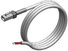
16.4 ft (5 m), P/N 20248
16.4 ft (5 m), P/N 30327
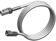
16.4 ft (5 m), P/N 20334
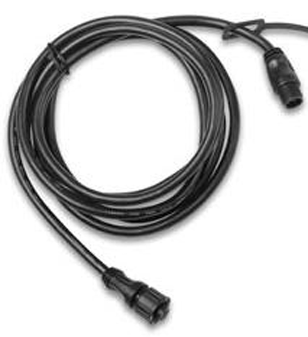
19.7 ft (6 m), P/N 30332
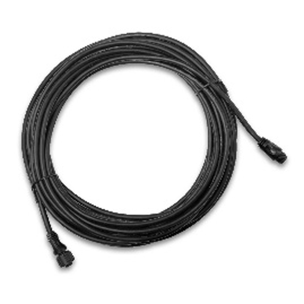
32.8 ft (10 m), P/N 30330
3.2 Motor Power Connections
AC Input Power Source Requirements
- Either of two AC input voltages are acceptable:
- 110 – 120 VAC (nominal) (+/- 10%), 1 Phase, 50/60 Hz, 30 A
- 208 – 230 VAC (nominal) (+/- 10%), 1 Phase, 50/60 Hz, 20 A
- A separate circuit breaker should be used for each Seakeeper Drive Box in multiple Seakeeper installations.
- The AC power source used must sustain 3500 W power for the spool-up operation of the Seakeeper 5.
AC Power Input Connection Instructions
AC Input Cable (3 X 10 AWG or 3X 0.6mm2 CSA), 10 ft (3 m) length, Seakeeper supplied pre-installed.
- Locate AC Input Cable for AC power input to the Drive Box.
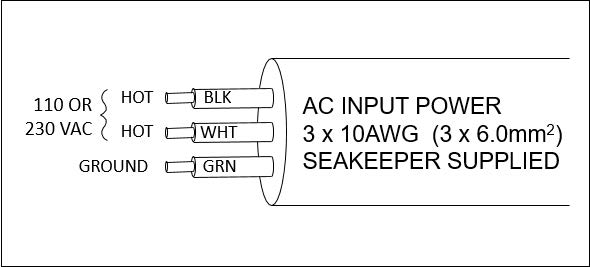
- Connect AC wires in to a 230 V, 20 A (or 110 V, 30 A), double-pole Circuit Breaker at an AC power distribution panel.
3.3 Control Power Connections

Reversing polarity on the DC power input to the Seakeeper can result in damage to electronics in the control system.
Low Current 12 V Power Source Requirements
- One 12 VDC, 15 A (Customer supplied) for Seakeeper Control Power.
- A dedicated breaker should be used for each 12 VDC load on the Seakeeper: one breaker for Control Power and one breaker for Seawater Pump power (Drawing No. 90982).
- A dedicated breaker should be used for each Seakeeper‘s Control and Seawater Pump power if multiple units installed.
12 VDC Control Power Connection
- Install Seakeeper provided DC Power Input Cable, P/N 20248 (Drawing No. 90982).
- Route DC Power Input Cable to DC Power Distribution Panel.
- Terminate positive (B+, Red) conductor to +12 VDC.
- Terminate negative (B-, Black) conductor directly to battery negative or negative bus terminal.
- Before connecting DC Power Input Cable to Seakeeper wire harness, check for proper voltage and polarity with a multimeter using figure below.
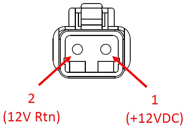
Contact Assignments (front)
- Connect control power cable to 12 VDC power input connector (labelled “INPUT POWER”) on the Seakeeper, Deutsch DTP04-2P connector.
3.4 Seawater Pump Power Connections
Reversing polarity on the DC power input to the Seakeeper can result in damage to electronics in the control system.
DC Seawater Pump Power Source Requirements
- One 12 VDC, 15 A (Customer supplied) for DC Seawater Pump.
- A dedicated breaker should be used for each 12 VDC load on the Seakeeper: one breaker for Control Power and one breaker for the DC Seawater Pump power (Drawing No. 90982).
- A dedicated breaker should be used for each Seakeeper‘s Control and Seawater Pump power if multiple units installed.
DC Seawater Pump Input Power Connection
- Install Seakeeper provided DC Seawater Pump Input Cable, P/N 30327 (as shown in Drawing No. 90982).
- Route Seawater Pump Input Cable to DC Power Distribution Panel.
- Terminate 16 AWG positive (B+, Red) conductor through 12 VDC dedicated overcurrent protection device (customer supplied), maximum of 15 A, to dedicated battery isolation switch.
- Terminate 16 AWG negative (B-, Black) conductor directly to battery negative terminal or DC main negative bus bar.
- Before connecting Seawater Pump Input Cable to Seakeeper wire harness (at “SW PUMP VDC IN”), check for proper voltage and polarity with a multimeter using figure below.
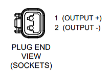
- Connect Seawater Pump Input Cable to “SW PUMP VDC IN” connector on the Seakeeper wire harness Deutsch DT04-2P connector.
DC Seawater Pump Output Power Connection
- Connect Seawater Pump Output cable (P/N 20334) to the Seakeeper 5 “SW PUMP VDC OUT” connector.
- The Seawater Pump Output cable is a 2 X 16 AWG cable, 16 ft (5 m) length, with a size 16 female Deutsch plug.
- The Seawater Pump Output cable is a 2 X 16 AWG cable, 16 ft (5 m) length, with a size 16 female Deutsch plug.
- Pumps rated at 12 VDC, 15 A maximum, customer-supplied, must be configured with a Deutsch DT series, 2-pin receptacle to mate with the connector shown in figure below.
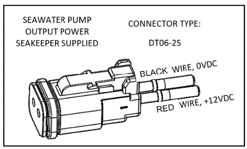
- The Seawater Pump Output cable must be routed and installed in the vessel from the Seakeeper “SW PUMP VDC OUT” connector (male) to the DC seawater pump cable Deutsch connector (female).
- Connect Seawater Pump Output cable plug (female) to the customer-supplied receptacle (male). The recommended wiring is shown in figure below.
- Contact Seakeeper if desired to install customer-supplied relay on Seawater Pump Output cable to power Seawater Pump.

3.5 Electrical Equipment Ground Connections
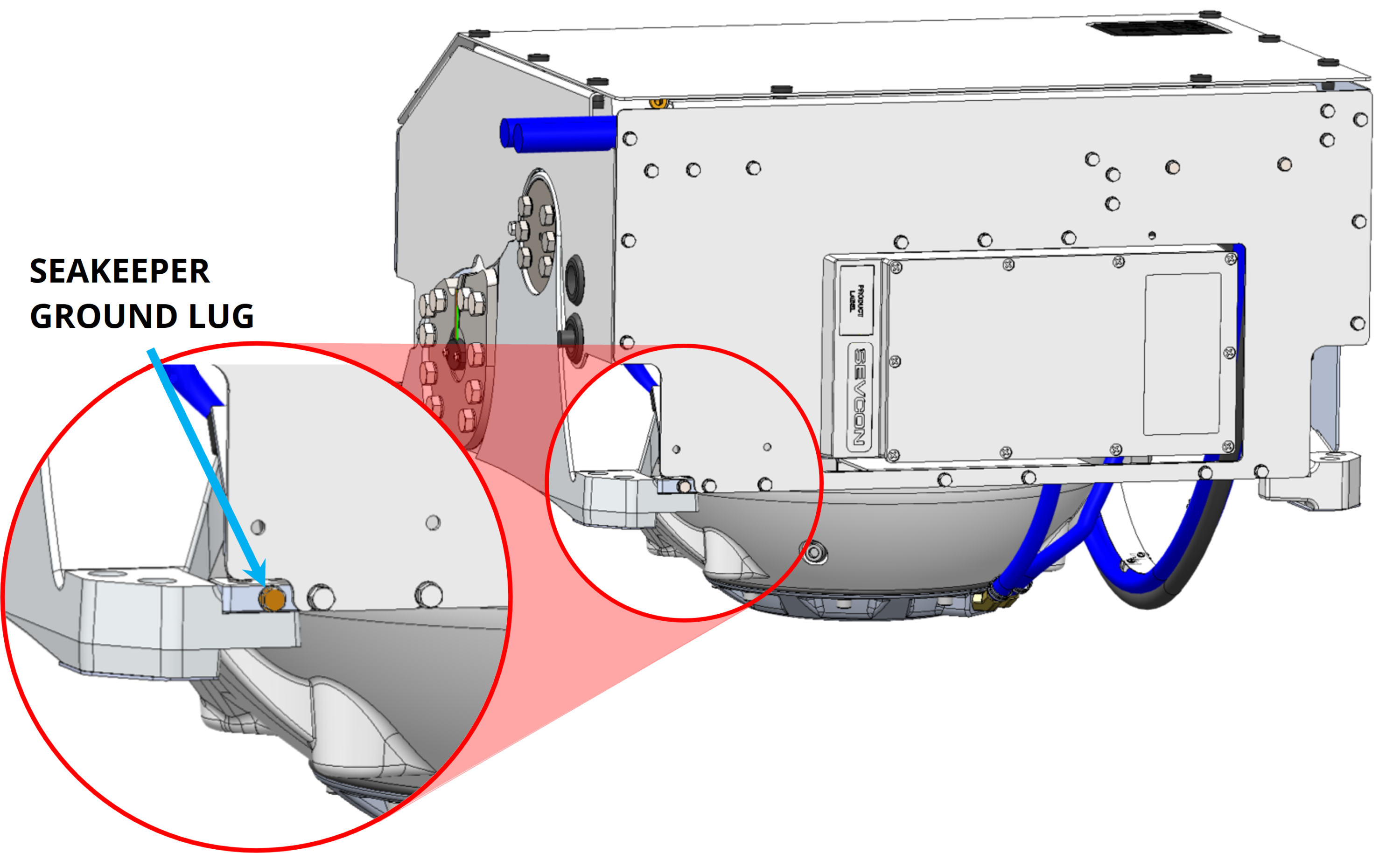
- Connect the Seakeeper foundation ground to vessel ground as shown in figure below.
- install Ground Cable (10 AWG or 6.0 mm2, customer-supplied) from the M6 brass ground stud on the Seakeeper rear brace to a suitable vessel ground.
- EN/IEC 60204-1: 2016 Clauses 6.3.3 and 8.2.3
- ABYC E-11 July 2021 Clauses 11.5.2 and 11.17
NOTE: USE ONLY THIS LOCATION TO GROUND THE SEAKEEPER TO THE VESSEL GROUND.
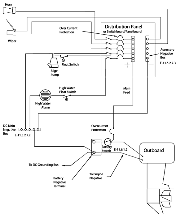
- Ground should be made with the vessel bonding system, if available. However, the ground is not referring specifically to a bonding system but for outboard boats generally refers to the outboard engine negative terminal. Per ABYC E-11 (2018), Clause 11.5.2.7.4: If the negative side of the DC system is to be connected to the ground, the connection shall be made only from the engine negative terminal, or its bus, to the DC grounding bus. This connection shall be used only as a means of maintaining the negative side of the circuit at ground potential and is not to carry current under normal operating conditions.
- A proper ground connection is critically important for corrosion protection and helps to ensure the ignition protection of the unit by ensuring it does not carry any stray current.
3.6 ConnectBox Connections
Reference Documents:
- 90982 – Seakeeper 5 Cable Block Diagram
- Seakeeper MFD Compatibility Technical Bulletins:
Seakeeper 5 Display Options
A multi-function display (MFD) is required with the installation of a Seakeeper 5 to support the full functionality of the unit through the Seakeeper App in addition to the ConnectBox. The Seakeeper App provides an interface for controlling the Seakeeper or viewing the Settings, Service, Info, and Alarm pages. The Seakeeper ConnectBox can be helm-mounted to provide an additional interface for the control of the Seakeeper but does not replace the need for a compatible MFD display.
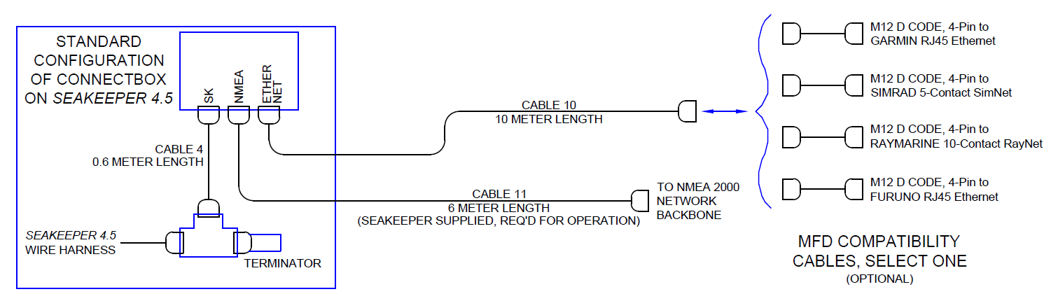
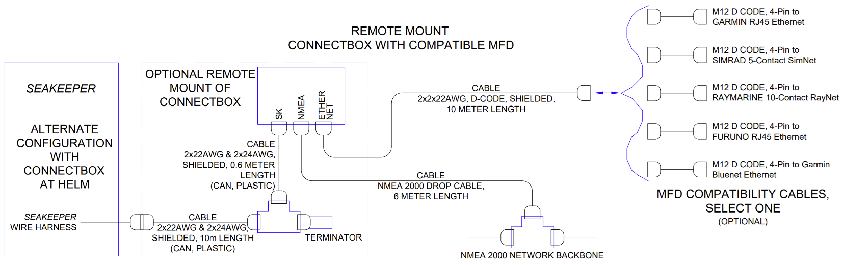
The following figure provides a schematic of the two display options. The subsequent sections outline the instructions and references for connecting the Seakeeper to each of these display options.
Connecting to a Compatible MFD
- The Seakeeper 5 can be connected to a variety of available MFD systems. Refer to the Technical Bulletins Section of the Seakeeper Technical Library for manufacturer specific MFD compatibility technical bulletins.
- MFD specific Technical Bulletins will be updated regularly as new MFD systems become compatible. Currently GARMIN, RAYMARINE, SIMRAD, and FURUNO offer compatible MFD models.
- Once a compatible MFD has been selected, refer to the appropriate manufacturer specific Technical Bulletin for integration instructions.
- Connect Seakeeper-supplied Ethernet adapter cable 10, D-Code 10 m cable to MFD manufacturer-specific Ethernet adapter cable. Custom Ethernet cables for specific MFD manufacturers are available through Seakeeper and must be purchased with the Seakeeper if connecting to an MFD.
ConnectBox Helm Mounting – Optional
- Console space required: Approx. 3.41 L x 4.15 W in. (87 x 106 mm).
- Mounting Instructions, Surface Mount: See Drawing No. 90558 – Seakeeper ConnectBox Helm Mounting Kit, for details. Seakeeper ConnectBox 3D Model available upon request.
- Mount ConnectBox Replacement Blank insert into Seakeeper 5 top cover at the original location of the ConnectBox.