Mechanical Installation Manual (750, 750 Quad)
5. Identify Installation Location
Installation Location Introduction
The performance of the Seakeeper Ride system is a direct result of the proper mounting location of the Controllers. It is vital to abide by the criteria in the Seakeeper Ride Installation Location Guide to choose the optimal mounting point for the Controllers. Optional use of the Seakeeper Ride 750 Controller Tool will assist with locating where the Seakeeper Ride system will sit on the boat Hull and how much room it will take in order to install.
For new production installations, please consult with the Seakeeper Applications Engineering Team or a naval architect for the proper location of the Seakeeper Ride Controllers according to the hull shape, hull type, engine configuration, and other relevant application details.
Note: Seakeeper has adopted a notation of the following to describe multiple controller installations:
| P1 | Port 1 | Port Outside |
| P2 | Port 2 | Port Inside |
| S2 | Starboard 2 | Starboard Inside |
| S1 | Starboard 1 | Starboard Outside |
Details for the inside and outside controller beam wise locations will follow.
For refit installations, please review the following sections to determine the ideal location for the Seakeeper Ride Installation.
5.1 Longitudinal Location
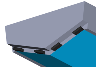
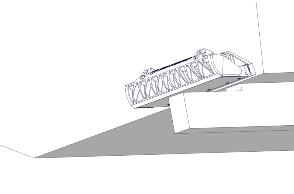
The Seakeeper Ride Controllers will be mounted to the transom, the approximately vertical surface at the aft end of the running surface, as shown in figures below.


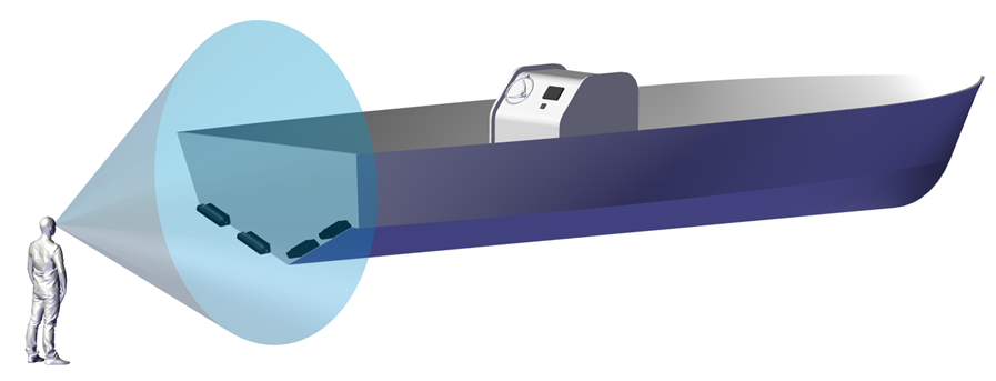
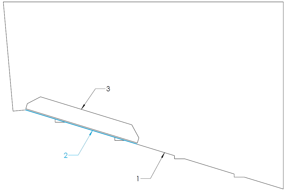
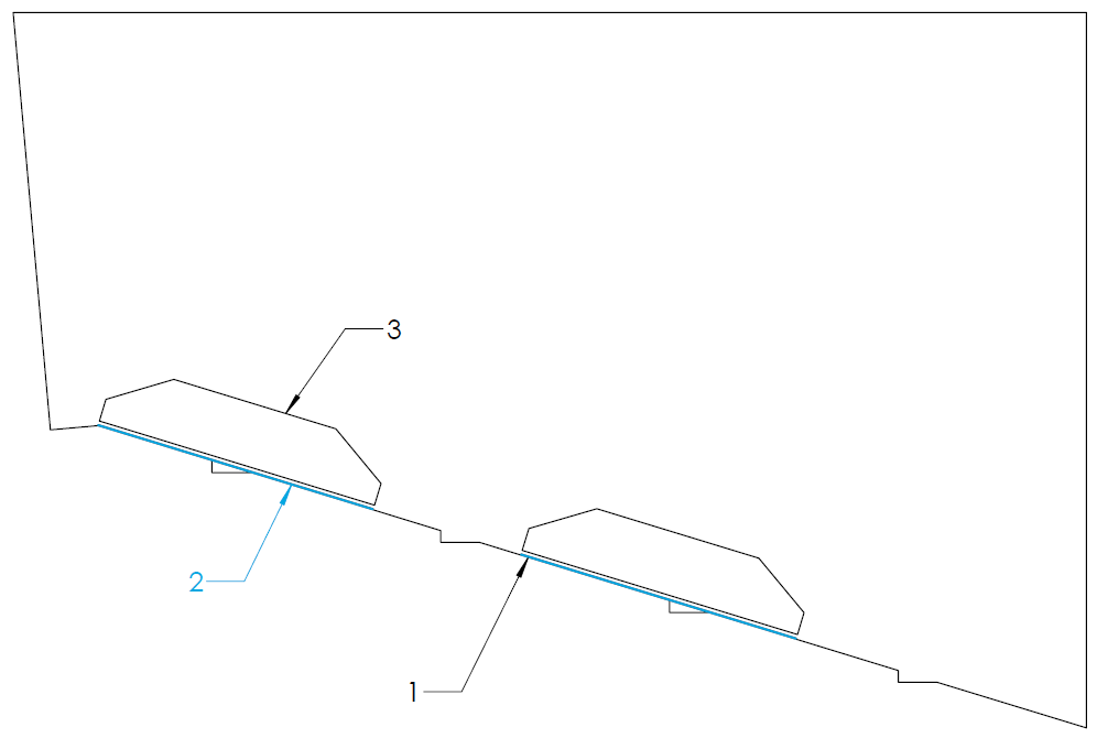
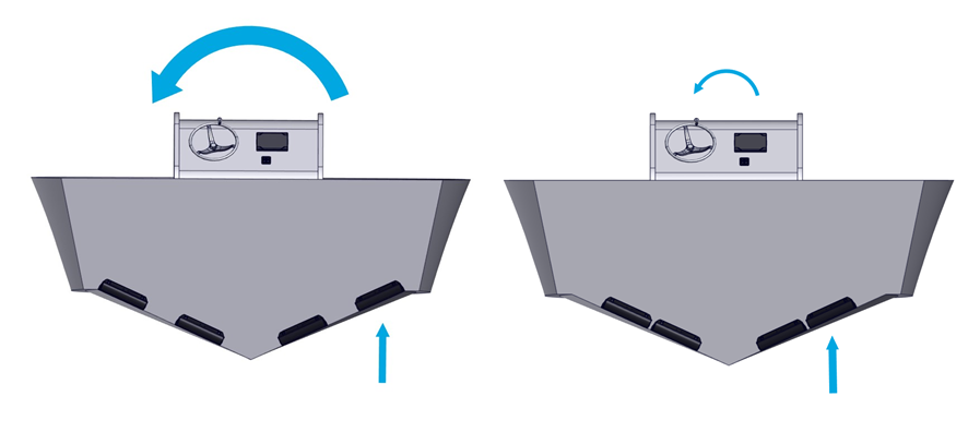
In Quad Controller installations, the outer Controllers, P1 and S1, may be installed at a different longitudinal location from the inner Controllers, P2 and S2. All Controllers must be flush with the running surface of the hull, highlighted in blue in the examples below.
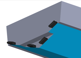
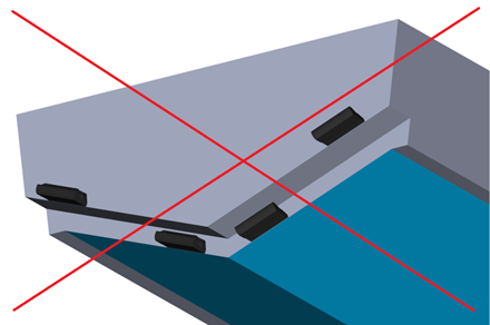
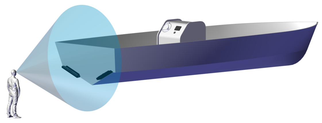
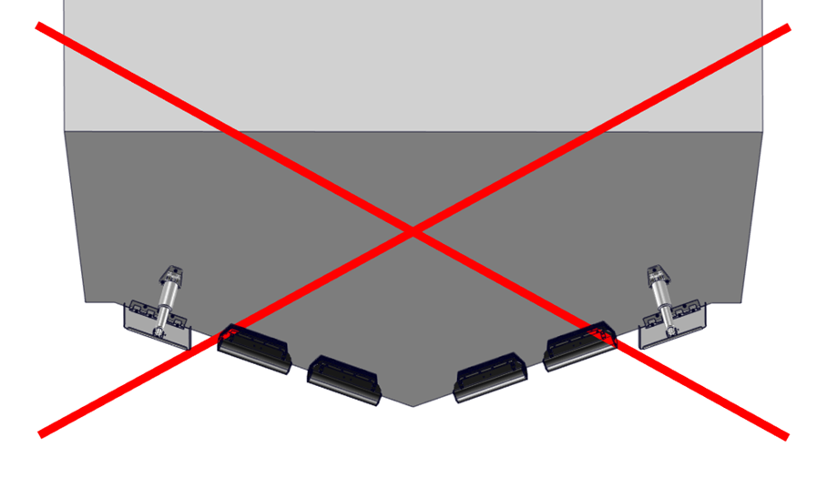
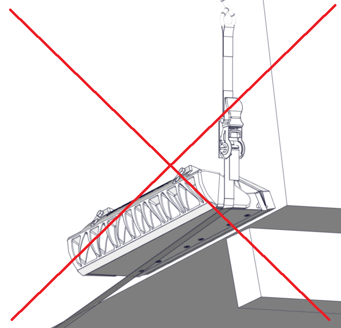
If any of the Controllers are installed above the running surface of the hull, they will not make contact with the water while at speed and be unable to influence boat motion as intended. See the example below of this type of incorrect installation.
5.2 Vertical Location
Seakeeper Ride’s Controllers must be mounted so that the bottom surface of the Seal Plate (Item Number 2 below) aligns flush and parallel with the hull bottom. The goal is to have the Seal Plate acting like an extension of the hull bottom. The Seal Plate’s location is determined by the Transom Plate (Item Number 8 below), which is affixed to the transom and adjusted up and down during installation to allow for fine-tuning the location.
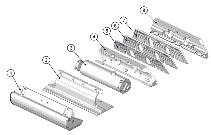
1) Blade
2) Seal Plate
3) Rotary Actuator
4) Actuator Plate
5) 5 Degree Wedge Plate
6) 4 Degree Wedge Plate
7) 3 Degree Wedge Plate
8) Transom Plate
Figure 8 – Seakeeper Ride 750 Controller Constituent Parts
The Ride Reference Line (RRL) is a guide for where the bottom of the Controller should be when mounted. The RRL is a representation of the bottom edge of the transom where it meets the running surface of the hull. Because of the unique shapes of different hulls, the RRL may not follow the bottom edge of the hull exactly. The following examples give guidance on where the RRL should lie on hull bottoms that are not perfectly straight.
An example transom with an exaggerated radius is shown below. The RRL is shown in blue and is the intersection of the two straight edges.
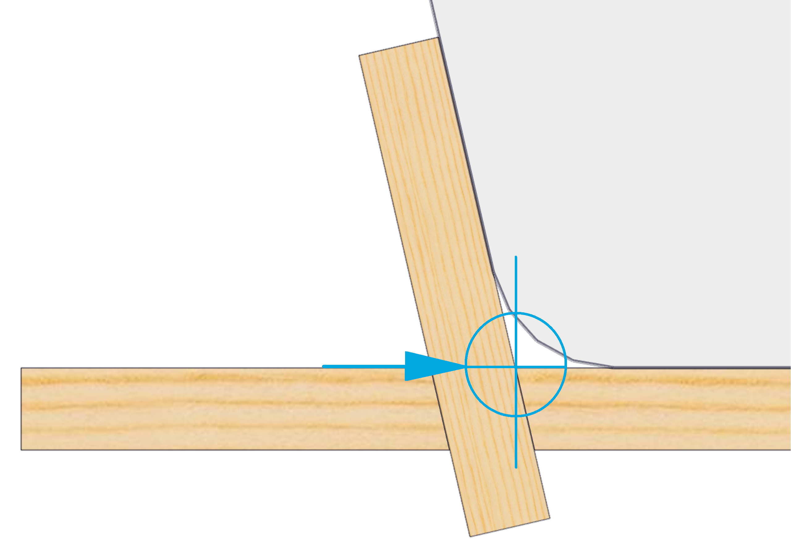
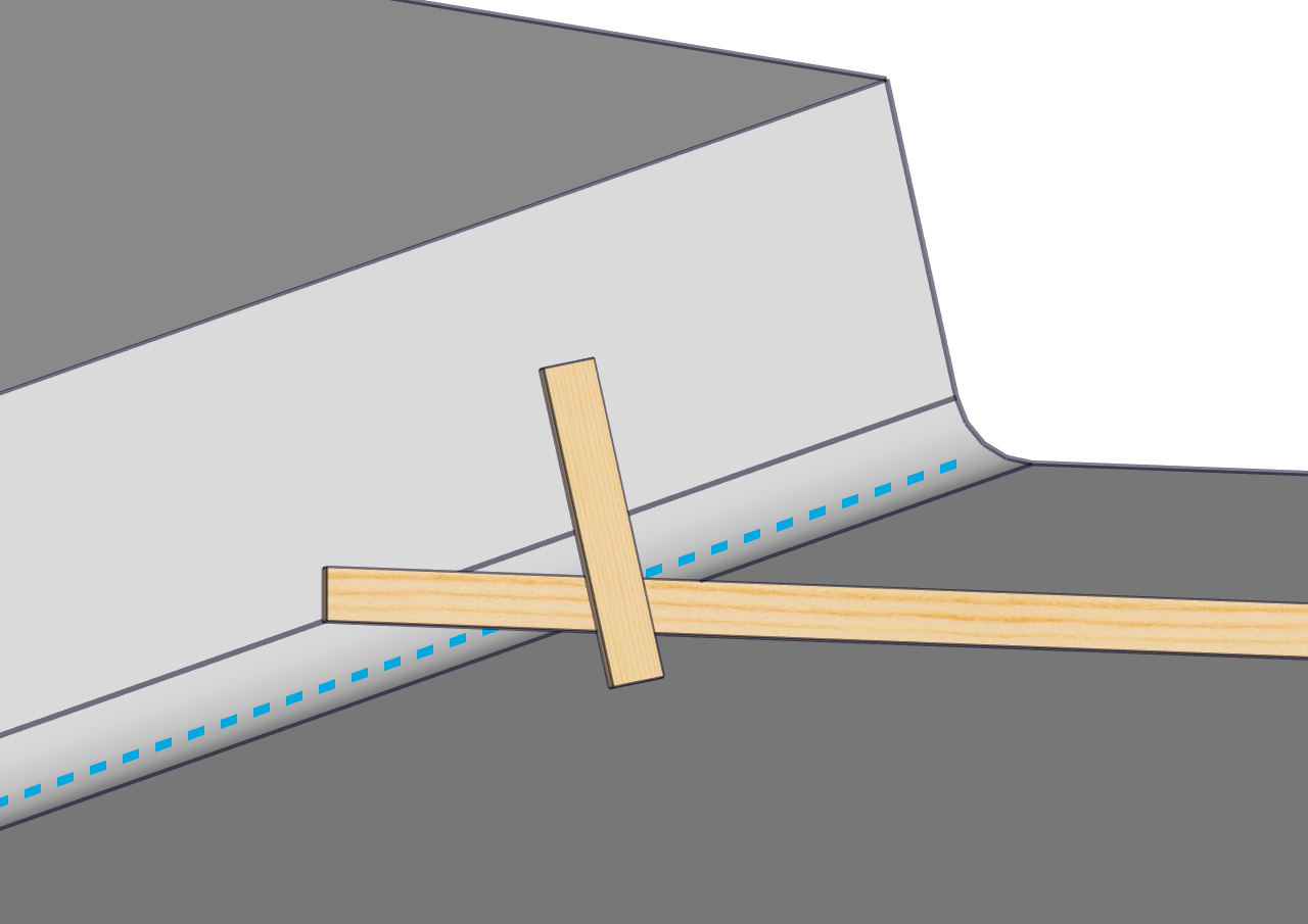
Figure 9 – Finding Reference Line with Straight Edges
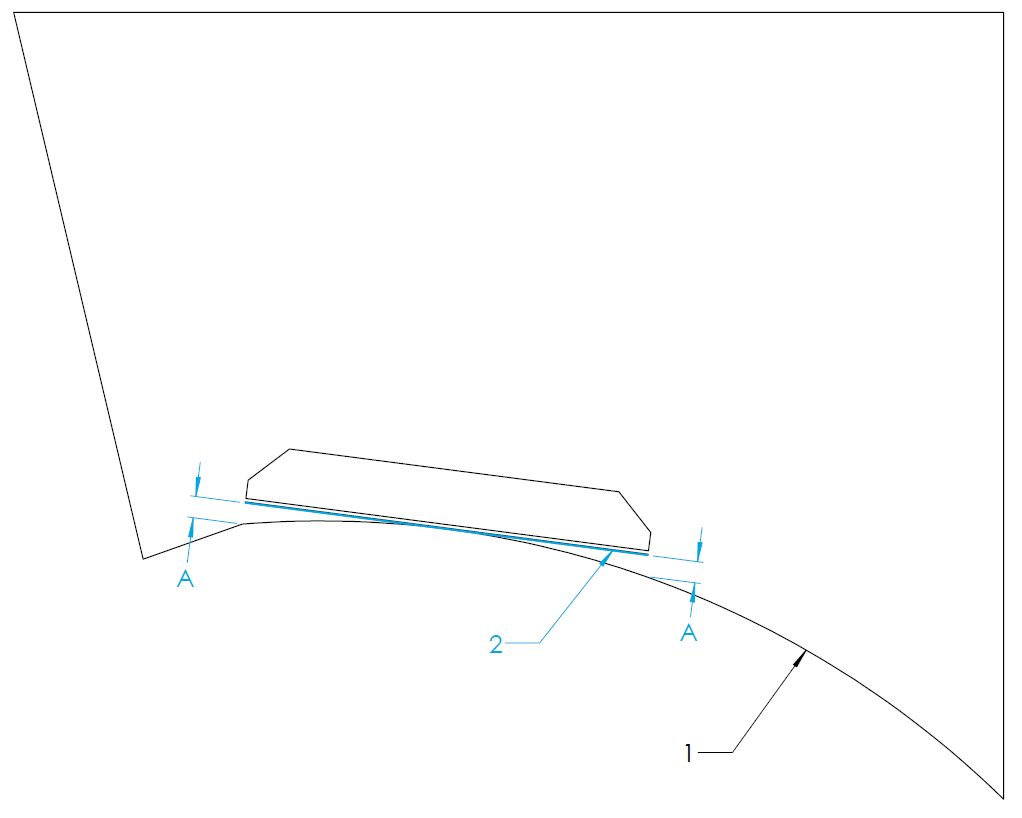
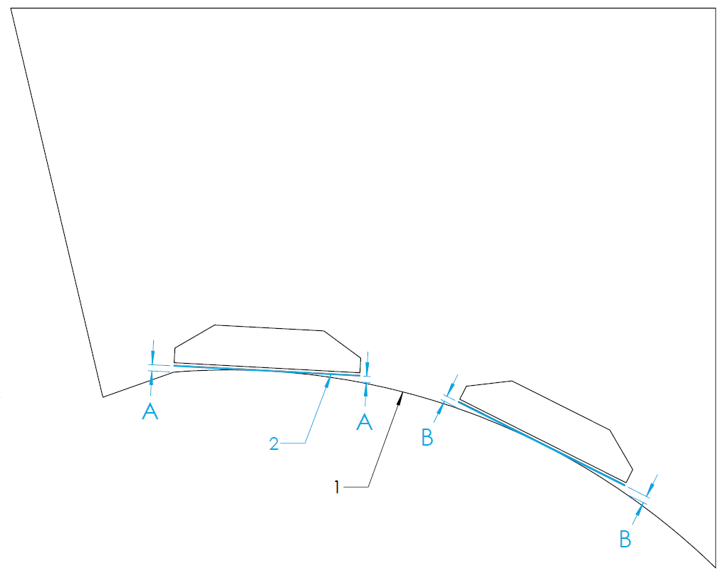
Figure 12 to Figure 19 in this section show a view from the stern of the vessel looking toward the bow. Label 1 indicates the bottom of the hull, Label 2 indicates the RRL, and Label 3 indicates the outline of the Transom Plate.
Strakes
Note: In this instruction manual the term ‘Strake’ is regarding a portion of the hull bottom which has an abrupt change in deadrise angle in comparison to the greater hull bottom. Sometimes referred to as ‘Lifting Strakes’ or ‘Spray Strakes’ it does NOT concern Chines.
For hulls with strakes, they can be ignored for the placement of the equipment and determination of the RRL. Strakes which extend all the way to the transom can reduce the authority of the Seakeeper Ride equipment. Terminating the strake at least 12 inches forward of Ride maintains full system authority.
Concave and Convex Deadrise
The Seal Plates (Item Number 2 in Figure 5) have a straight design. Some hulls may have curvature along the deadrise which will cause the Seal Plate to show gaps between the deadrise at either the ends or center of the plate. The following sections describe how to find the RRL in concave and convex deadrise hulls.
Concave Deadrise
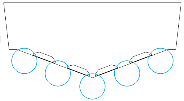
For vessels with concave curvature, the Seal Plate should be mounted such that the center of the Seal Plate is flush to the hull bottom and the ends of the Seal Plate are equidistant from the hull bottom (measurement A and B in the figures below). Measurement A and B must be 0.5 in. or less. More curvature decreases Seakeeper Ride Authority. For vessels with concave curvature, the RRL is defined as the tangent to the hull bottom, shown by the blue line.
Convex Deadrise
For vessels with convex curvature, the ends of the Seal Plate should be mounted flush with the hull bottom with a gap between the center of the Seal Plate and the hull bottom (measurement A and B in the figures below). Measurement A and B must be 0.5 in. or less. More curvature decreases Seakeeper Ride Authority. For vessels with convex curvature, the RRL is defined as the straight line along the transom between inboard and outboard ends of the seal plate’s destination.
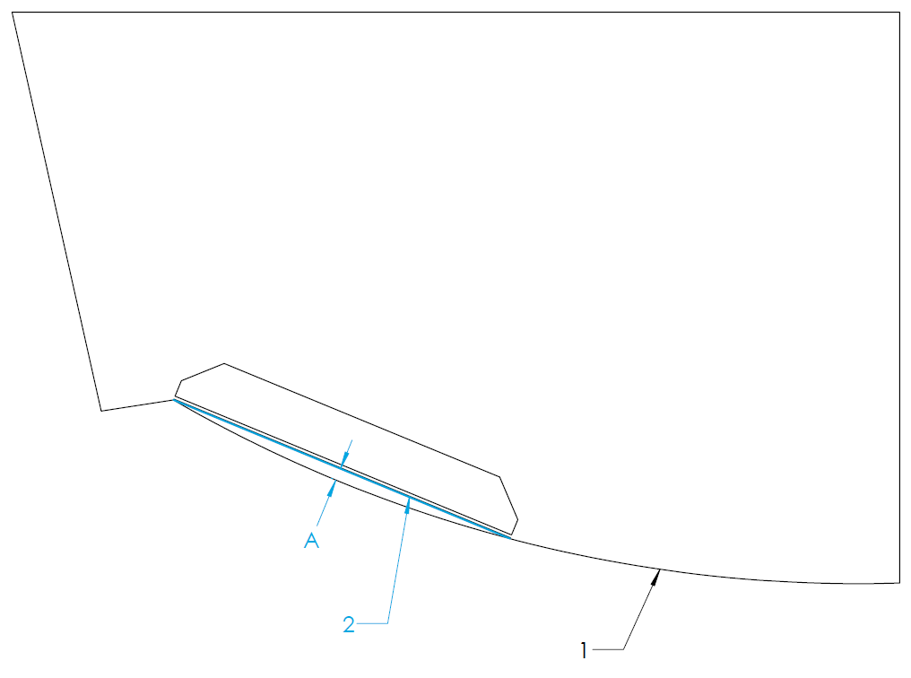
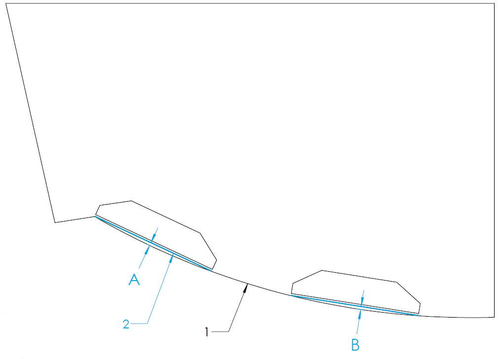
Figure 17 – Convex Hull Bottom RRL and Transom Plate Trace (Quad Controller)
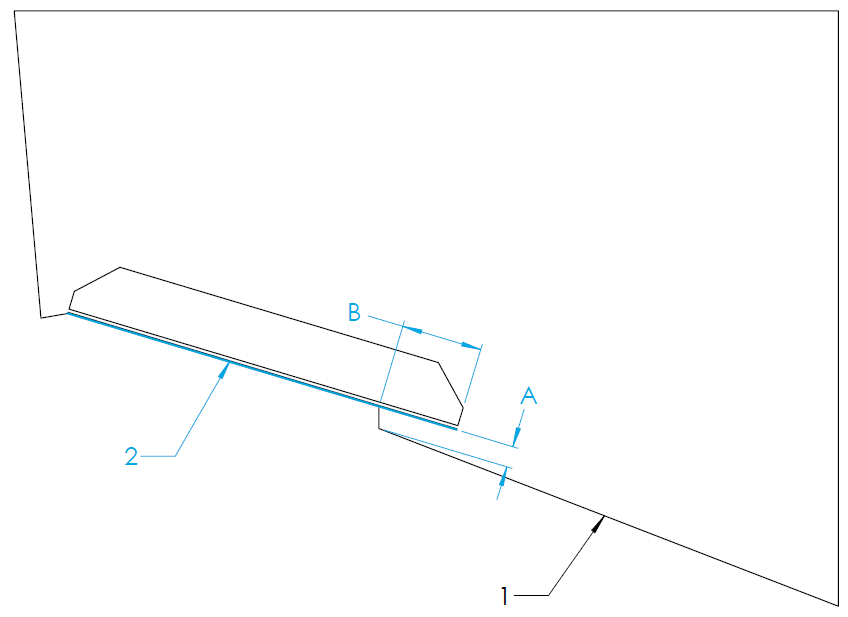
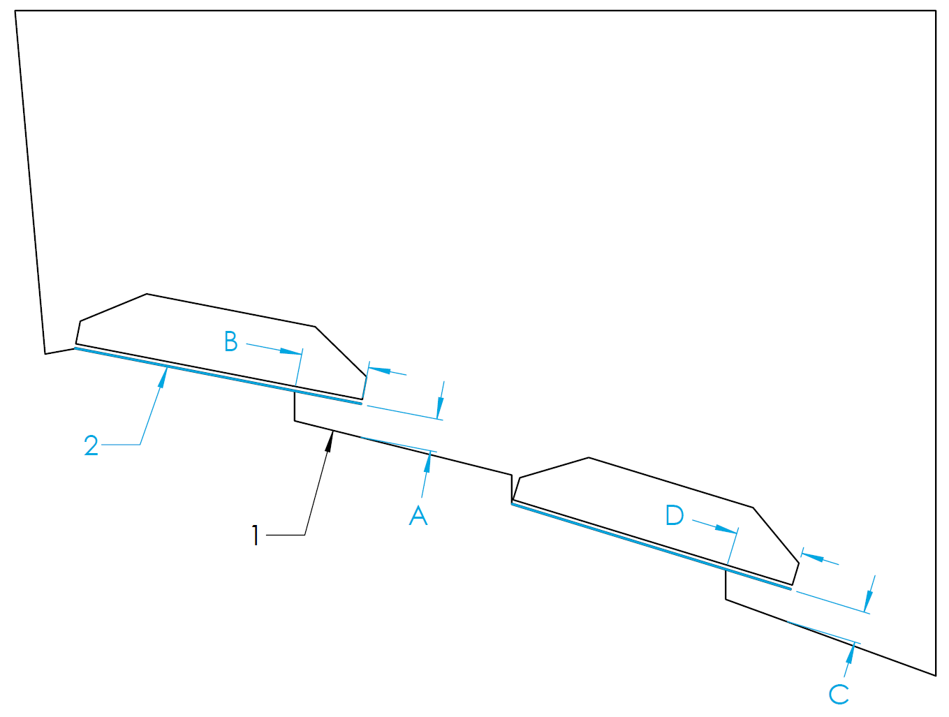
Variable Deadrise
Variable deadrise hulls are those where the running surface has breaks that run longitudinally. Generally, these hulls have decreasing deadrise angle in each successive panel moving outboard from centerline. Seakeeper Ride Controllers are capable of being mounted on variable deadrise hulls, so long as the following mounting conditions can be met:
- Distance from inboard edge of the Controller to the running surface of the hull (Dimension A and C in the figures below) is 0.75 in. (19 mm) or less. This requirement only applies to vertical changes beneath the Controller.
- The portion of the Controller extending inboard of the deadrise break (Dimension B and D in the figures below) is 3 in. (76 mm) or less. For Quad Controllers, the overhanging portion of both Controllers added together must be 3 in. (76 mm) or less (In the figure below, B + D = 3 in. max).
In hulls with a variable deadrise, the RRL is the highest portion of the deadrise that the Seakeeper Ride system will cover. See the figure below for this position. Because performance may degrade rapidly if these conditions are not met, please reach out to Seakeeper for guidance in this instance if a boat falls outside these parameters.
5.3 Beam-Wise Location
There are several hull features that should be considered when determining the location of the Controllers in a beam-wise orientation.
As a general rule, the OUTSIDE MOST Controllers must be mounted as far outboard as possible, up to the chines (if the hull has chines). Details on the precise beam wise location is in the following sections.
Inboard Controllers should be mounted according to different priorities and should follow section 5.4.

ATTENTION: Mounting the OUTSIDE MOST Controllers towards the centerline of the boat reduces the leverage the system has on the boat and severely reduces roll performance.
Chines
Note: In this instruction manual the term ‘Chine’ is regarding the intersection of the hull bottom and hull side with an abrupt change in deadrise angle. This is sometimes referred to as ‘Reverse Chine’.
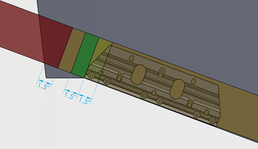
Based on the considerations of engine spacing and transom appendages, some installations will require the Controllers to extend outboard of the inboard edge of the chine. An overlap of the outboard chine of 1.5 in. (38 mm) is acceptable. For overlaps greater than 1.5 in. (38 mm), performance may degrade rapidly. The figure below illustrates placement of the outboard edge of the Controller with the following color code:
- Green (Outboard of chine up to 1.5 in. (38 mm)) – Ideal
- Yellow (Inboard of chine up to 1.5 in. (38 mm)) – Good
- Orange (More than 1.5 in. (38 mm) from chine) – Acceptable*
- Red (Overhanging Hull Side) – Unacceptable
*Controllers must NOT be mounted far enough inboard to reduce leverage, as outlined above.
Hull Side Spacing
It is possible to have an installation where the Controller is mounted too far outboard causing water flowing around the hull side to interfere with the Controller and substantially reduce performance.
To avoid this issue, the Controller should be mounted at least 1.5 in. (38 mm) inboard of the hull side, as shown below.
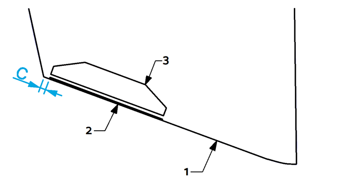
Figure 23 – Hull Side Clearance
Propeller Tunnels
In the event a hull has propeller tunnels and there is not enough beam to install a Dual Controller system outboard of the tunnel, it is possible to utilize a Quad Controller system.
The outboard controllers should be mounted outboard of the propeller tunnel.
The inboard controllers could be mounted in 2 locations. The inboard controller can be mounted on top of the propeller tunnel if there is a straight section of the tunnel to match with the controller seal plate. Alternatively the inboard controller can be mounted on the deadrise inboard of the propeller tunnel.
Review of other hull features like convex and concave hull bottoms and variable deadrise should be considered with this placement.
5.4 Engine Spacing
NOTE: For all installations it is vital to ensure the Ride equipment is mounted such that the propulsion equipment is able to articulate through its full range of travel including trim, tilt and steering without any contact between Ride and propulsion.
Inboard and Podded Propulsion Applications
For Inboard and Podded Propulsion boats where Ride is mounted aft of the propeller, the Ride mounting location should not take into consideration the propellers. Podded Propulsion includes but not limited to Mercury/Cummins Zeus Drive and Volvo IPS Drive.
Ride recommends utilizing Dual Controllers if the hull shape allows. In the event the hull has propeller tunnels or other novel hull features which prevent Dual Controller installation should consider Quad Controllers to allow best Ride authority over the hull. Testing has shown comparable performance in Dual and Quad Controller installations.
Outboard and Sterndrive (Inboard/Outboard) Applications
For Outboard and Sterndrive (I/O) applications the following guidance should be used to determine best locations for controllers relative to the propellers. Location must consider hull shape and propeller location in these boats.

NOTE: Seakeeper has performed successful testing with Seakeeper Ride overlapping propellers significantly further than indicated below; however, because of the infinite variables (engine height, engine trim, engine longitudinal offset from Seakeeper Ride Controllers, propeller selection, propeller rotation, sea conditions, loading conditions, vessel characteristics, and more) which impact the interaction between Seakeeper Ride and propulsors, Seakeeper cannot provide more specialized guidance or blanket recommendation to install with more propeller overlap than indicated below. If the Builder, Owners, or Operators choose to install the Seakeeper Ride Controllers with more propeller overlap than indicated in the figure below, it may result in rpm/coolant fluctuation and/or engine faults. Please see the Operation Manual for additional detail on Seakeeper Ride’s potential impacts to propulsors.
Due to the Controllers potential to change water flow into the boat’s propellers, it is recommended the Controllers be spaced around the engines and propellers to the outboard most Controllers should be mounted as far from the propellers as possible. It is recommended that the inner edge of the Controller be mounted outboard of the diameter of the propeller tip (see the figure below). The line defining this instruction is the tangent line to the diameter of the propeller tip on the outboard side, perpendicular to the deadrise. Label 4 indicates the diameter of the propeller tip.
5.6.1 Three (3) Outboard or Sterndrive Engine Applications
For installations with Triple Outboards or Sterndrive (Inboard/Outboards (I/O)) we recommend the following guidance for locating the controllers:
Dual Ride Controllers on three (3) Outboard or Sterndrive Engine Applications
If Dual Controllers are selected, the controllers should be mounted as far outboard to the hull side as indicated in Section 5.3.
Quad Ride Controllers on three (3) Outboard or Sterndrive Engine Applications
If Quad Controllers are selected, the outside controller to be as far up the chine as possible.
The inside controller is to be centered between the engines. If there is Controller overlap of propellers, the inside controller should be such that the Blades of all four (4) controllers overlaps of all three (3) propellers evenly.
5.6.2 Four (4) Outboard or Sterndrive Engine Applications
For installations with Quad Outboards or Sterndrive (Inboard/Outboards (I/O)) we recommend the following guidance for locating the controllers:
Dual Ride Controllers on four (4) Outboard and Sterndrive Engine Applications
If Dual Controllers are selected, the controllers should be mounted as far outboard to the hull side as indicated in Section 5.3.
Quad Ride Controllers on four (4) Outboard and Sterndrive Engine Applications
If Quad Controllers are selected, the outside controller to be as far up the chine as possible.
The inside controller should be such that the Blades of all four (4) controllers overlaps of all four (4) propellers evenly. Measuring for this can be simplified by setting the the distance from the outboard engine centerline to the outboard controller centerline the same as the distance from the inboard engine centerline to the inboard controller centerline.
5.6.3 Five (5) Outboardor Sterndrive Engine Applications
For installations with Quint Outboards or Sterndrive (Inboard/Outboards (I/O)) we recommend the following guidance for locating the controllers:
Dual Ride Controllers on five (5) Outboard or Sterndrive Engine Applications
If Dual Controllers are selected, the controllers should be mounted as far outboard to the hull side as indicated in Section 5.3.
Quad Ride Controllers on five (5) Outboard or Sterndrive Engine Applications
If Quad Controllers are selected, the outside controller is to be centered between outboard propellers.
The inside controller should be such that the Blades of all four (4) controllers overlaps the center and middle propellers evenly.
5.5 Physical Space
Before beginning the installation, check that there is adequate space in the ideal location determined above. Some hulls may not have physical space for the installation of Seakeeper Ride. There may be some installations where brackets, lights, live well pickups, hull features, or similar components must be cleared or relocated to proceed with the installation.

Note: Seakeeper is not responsible for hull modifications performed when attempting to install Seakeeper Ride. It is the responsibility of the installer to determine reasonable modifications to prepare room for the Controllers without making undesirable changes to the boat. If unsure of installation details, contact a licensed marine engineer or naval architect before making significant boat modifications. Contact Seakeeper if additional help is needed.
The width of the Controller mounting footprint will vary depending on Controller size. See the figure and table below for dimensions to determine if there is adequate space on the boat’s transom. The clearance between the bottom of the hull and any surface above where the Controller will be placed is recommended to be at least 5 in. (127 mm). The exact height is dependent on the transom angle and resulting Wedge Pack build of the Controller. The Controller will extend aft of the hull by 8 in. (203 mm).
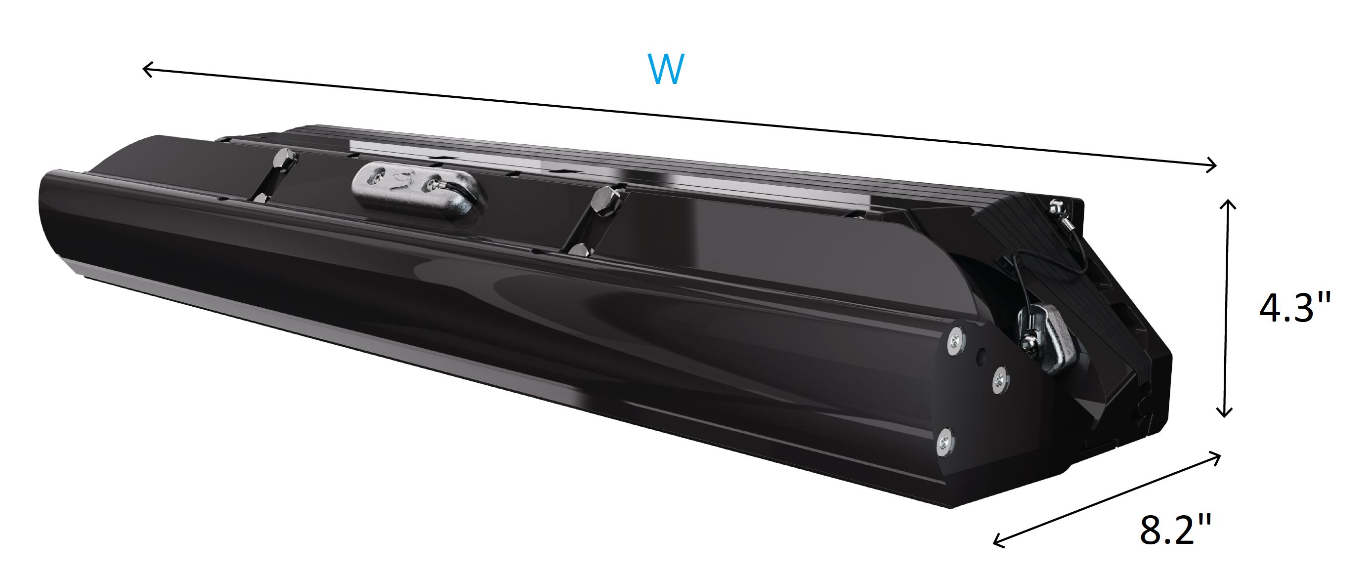
| Boat Length (ft) | 37-42 | 37-42 |
| Seakeeper Ride | 750 Dual | 750 Quad |
| Part Number | 90900 | 90882 |
| Width (mm) | 750 | 375 |
| Width (in.) | 30.1 | 15.4 |
Table 2 – Controller Width
Refer to the Controller Footprint and Envelope page for higher detail dimensions.
5.6 Loading and Storage Details
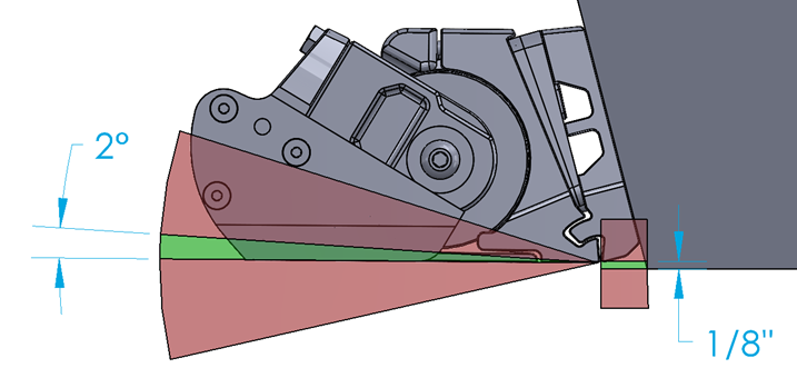
The Controllers should not be installed where they will carry any load of the boat while on bunks (i.e. a trailer, storage rack, or fork truck). If there is concern with bunks loading the Controllers:
Mount Upward – Seakeeper Ride can be mounted up to 1/8 in. (3.2 mm) up from the bottom of the hull with negligible effect on system performance.
Angle Upward – Seakeeper Ride can be mounted up to two (2) degrees angled upward from the bottom of the hull with negligible effect on system performance.
One or both of these mounting tolerances may be used to keep Seakeeper Ride from contacting the bunks and increase the longevity of the system.
Seakeeper Ride will automatically retract the Blades when coming to a stop, meaning that they will be flush with the rest of the Controller and should not cause problems when placing the boat on bunks during normal operation in both Auto and Manual modes.
Setting Up the Trailer for Seakeeper Ride
Cut bunks short – If the bunks are too long, cut them to correspond with the end of the transom rather than extending aft.
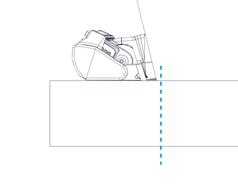
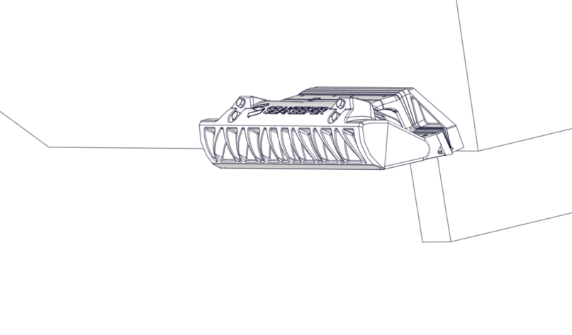
Figure 29 – Cutting Bunks Short
Cut bunks low – If the bunks cannot be cut shorter, bunks can be cut with a small recess below Seakeeper Ride to prevent excessive force on the Controller when going down the road.
Do Not Place Tie-Down Straps Across Seakeeper Ride – Consider moving straps to cleats or to a different tie down point.
5.7 Asymmetrical Details
Many boats are not perfectly symmetrical about the centerline, resulting in subtly different mounting locations and angles for each Controller. This is acceptable and may require different Wedge Plate angles used for port and starboard Controllers. Following this guideline for the correct installation location will result in a proper installation even if there are asymmetries in the hull.
5.8 Cable Entry
In the final details of the installation, the cable that powers and drives the Controllers must pass through the transom of the hull. The location for cable penetration will be based on available access to the transom on the interior.
Concealed Cable Entry
For concealed cable entry, route through either of the oval holes of the Transom Plate (highlighted in blue in the figure below). To utilize either location, you must be able to reach the hole from the inside to tighten the supplied cable gland and prevent water entering the hull.
As an example for internal routing, the figure below depicts a stringer shown with dotted lines that is preventing use of the inboard cable penetration. In this example, the outboard cable pass-through is available as indicated by the blue arrow. This can only be used if there is access on the interior side of the penetration.
Exposed Cable Entry
Locations outside the Transom Plate can be used as well. If the cable penetration location is below the waterline, the supplied cable gland must be used to ensure a watertight hull after the penetration.
This cable penetration method can be used in locations above the waterline as well.
Cable Lengths
In all cases, the supplied cable for the Controllers is limited to 10 ft (3 m). Carefully consider the cable routing and location of the Distribution Module to ensure both cables can connect to the Distribution Module.
Note: On 4 controller applications, there are 2 distribution modules. Any Controller may be connected to any Distribution Module and function correctly. It is therefore possible to have a ‘Port Side Distribution Module’ and ‘Starboard Side Distribution Module’ or an ‘Inside Most Distribution Module’ and ‘Outside Most Distribution Module’ depending on available space and cable lengths.