Maintenance Schedule
3.2 Bottom Painting 750-1500
To prevent marine growth and increase longevity of the components, the Seakeeper Ride Controllers may be coated in antifouling paint, also known as bottom painting. This is recommended if the boat will be in the water for more than two (2) weeks at a time. Follow the instructions in this document to ensure the best results when bottom painting Seakeeper Ride.
Choose a bottom paint that best fits the usage and storage of the boat. Avoid paints that contain metals for biocide, as it may cause corrosion damage to the stainless steel and aluminum components. Spray on paints are easier than roll on but may take more time in preparation to prevent overspray on undesired surfaces.
To bottom paint Seakeeper Ride Controllers:
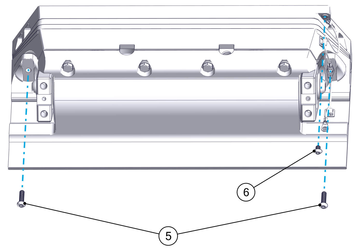
- Remove the front Blade anode by unscrewing the two (2) M5-0.8 screws.
- Remove the Blade by unscrewing the four (4) M8-1.25 screws and their washers.
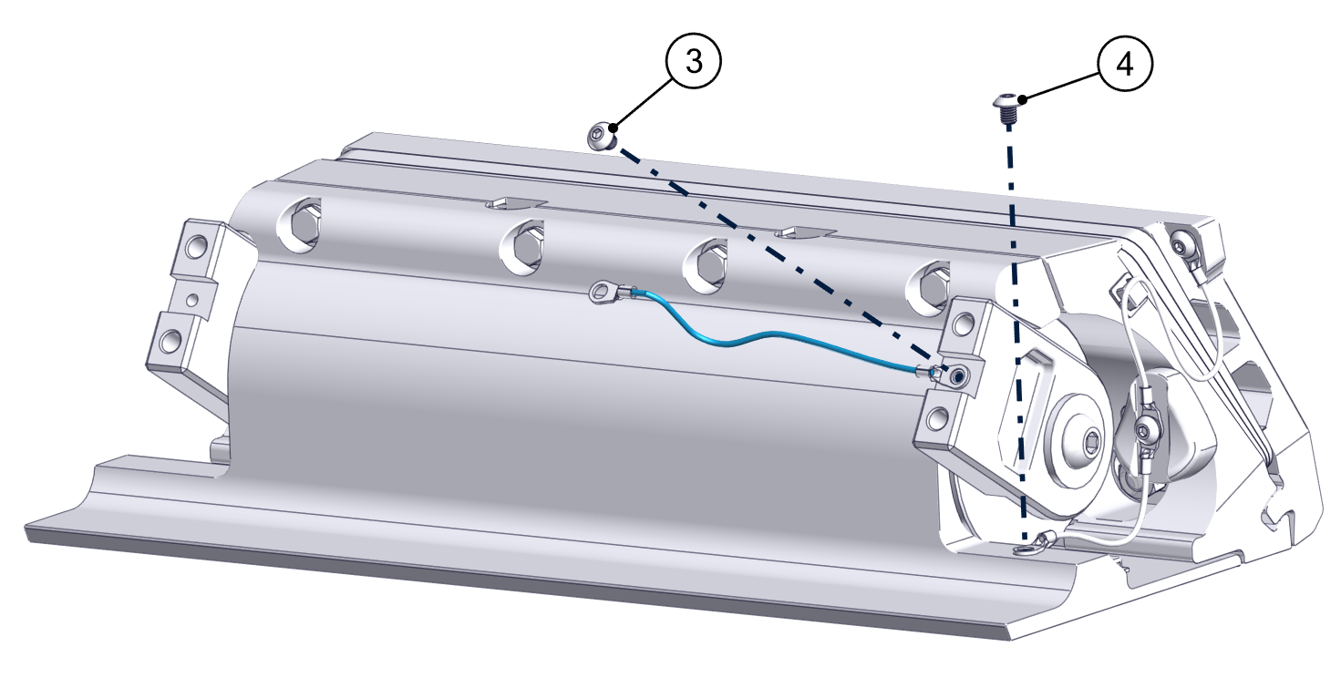
- Remove the Actuator Arm bonding wire by unscrewing the M5-0.8 screw.
- Remove the M5-0.8 screw securing the bonding wire to the Seal Plate.
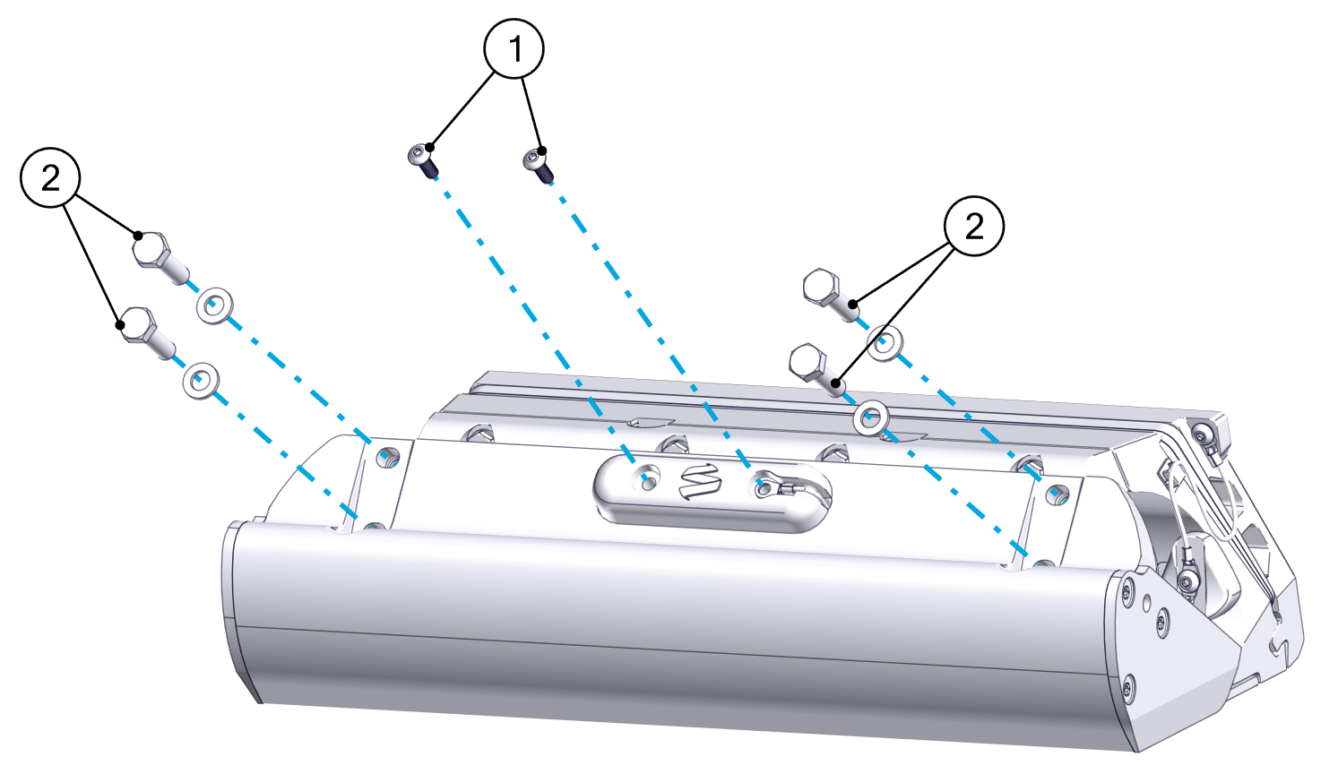
- Remove the two (2) Actuator Plate anodes by removing the M5-0.8 screws securing them. This will also free the bonding wire from the Actuator Plate to the Seal Plate.
- Remove the M5-0.8 screw securing the bonding wire to the Transom Plate to release the final bonding wire.
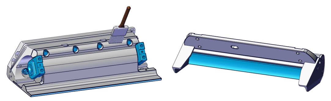
- Use masking tape to cover surfaces that will not be painted. This includes the inside of the Blade, trailing edge of the Seal Plate, stainless steel hardware and arms, and any part of the boat that will be left unpainted. Controller components that should be protected with tape are shown in blue in the figure below.
- Follow the instructions and recommendations associated with the paint being used for surface preparation on the coated aluminum parts (Seal Plate, Blade, Actuator Plate, Wedge Plates, and Transom Plate) supplied. The surface can be abraded using a scouring pad and wiped with alcohol to prepare them for paint adhesion. Be careful not to gouge, cut, or sand deeply into the coated parts. Removing the coating completely will expose the aluminum to water and corrosion.
Do not sand or scuff the stainless steel torque arm or aluminum body of the Actuator. Do not scuff or alter the inside of the Blade or trailing edge of the Seal Plate. The gap between these surfaces is precise and must remain at factory fitment. Surfaces that must not be scuffed are shown in blue in the figure above.
- Apply the selected bottom paint to the Blade and the rest of the Controller assembly. Do not paint the inside of the Blade and trailing edge of the Seal Plate. Adding paint to these surfaces will cause the parts to contact during operation and greatly reduce system performance. Avoid painting the stainless steel hardware and arms. Surfaces that must be left unpainted are shown in blue in the figure above. Paint all other accessible surfaces.
- Reattach the anodes, bonding wires and Blade by reversing the steps above. Be sure to use approved thread locker when reinstalling hardware. Torque these four (4) Blade bolts to 130 in-lbs (14.7 N-m) in an “X” pattern.