Controller Locator Tool Manual
Seakeeper Ride | Controller Locator Tool Manual
1. Introduction
Updated 5/11/2023

ATTENTION: The Seakeeper Ride Controller Locator Tool and instructions are for certified dealers and OEM boat installers.
This document is intended to give details and guidance for assembling and using the Seakeeper Ride Controller Locator Tool.
Due to the quantity of parts and careful installation requirements, set aside a clean workspace, take inventory of necessary tools and parts, and review the entirety of this manual before setting to work.
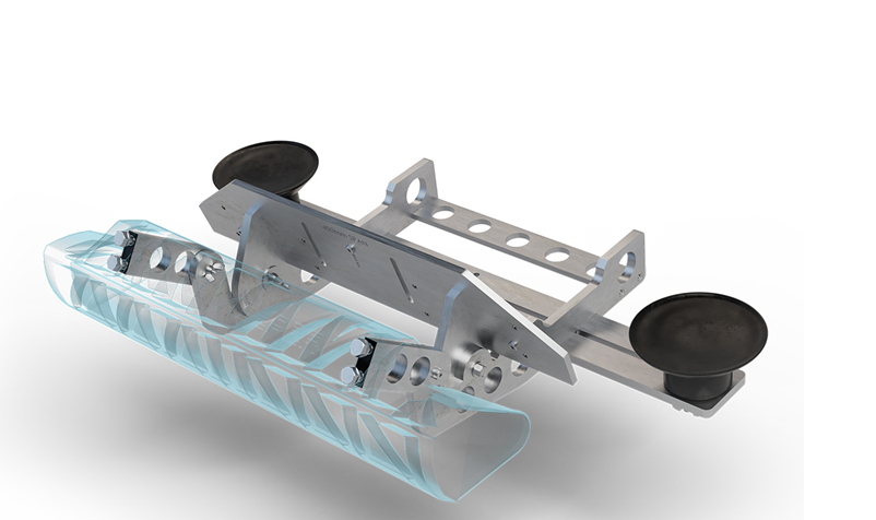
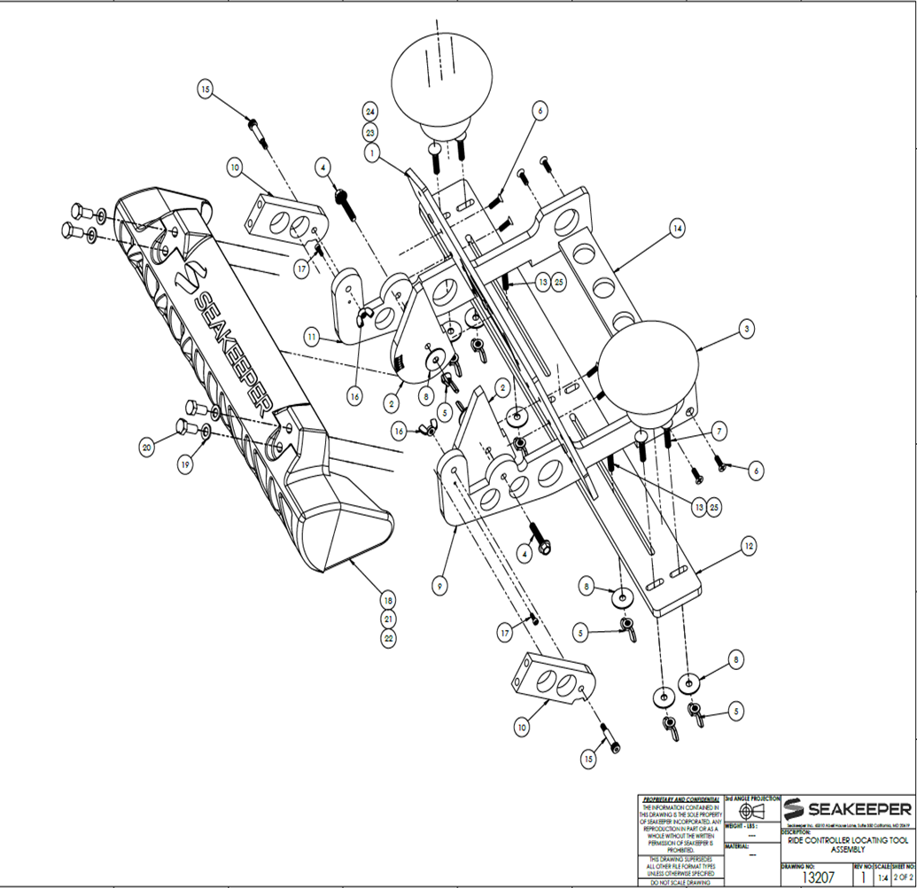
Figure 1- Seakeeper Ride Controller Locator Tool
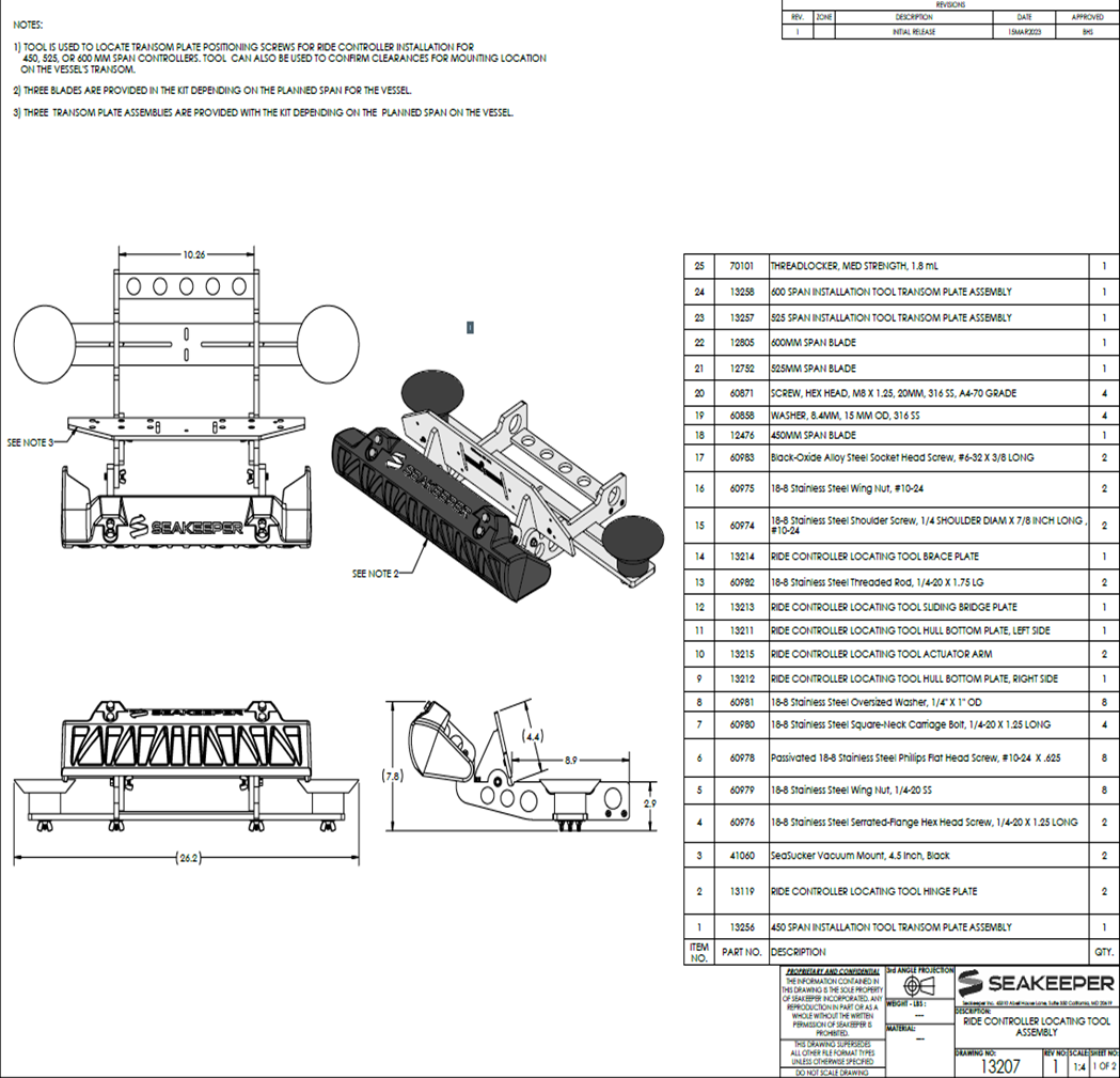
2. Controller Locator Tool Kit
The Seakeeper Ride Controller Locator Tool comes with all pieces and parts, but some assembly will be required before the tool can be used.
The Controller Locator Tool works for the installation of the Seakeeper Ride models: 450, 525, and 600 mm.
Three Blades are provided in the kit depending on the planned span for the vessel. Three Transom Plate assemblies are also provided with the kit depending on the planned span on the vessel.

Figure 2- Kit provided pieces.
3. Controller Locator Assembly
Assembly Steps:
- Review parts and make sure all parts are included and accounted for.
- Assemble the Locating Tool Hull Bottom Plate, right side (#9) to the Locating Tool Brace Plate (#14) by using 18-8 Stainless Steel phillips flat head screw, #10-24 x .625 (#6).
- Repeat previous step using the Locating Tool Hull Bottom Plate, left side (#11).
- Install the Locating Tool Hinge Plate (#2) to the Locating Tool Hull Bottom Plate (#9 & #11). Note: The Hinge Plate is interchangeable.
- Put the Locating Tool Actuator Arm (#10) to the end of the Locating Tool Hull Bottom Plate (#9 & #11). Note: The Black-oxide Alloy Steel Socket head screw, #6-32 x 3/8 long (#17) may be installed already. If it is not installed already, install first.
- Installation of the Transom Plate Assembly (#1) will be based on the size of the system the customer needs.
- Locating Tool Sliding Bridge Plate (#12) will be installed on the Bottom of the Two Studs from the Locating Tool Hull Bottom Plate.
- Assembly of the Sea Suckers will require the removal of the four phillips head screws on the Bottom of the Sea Sucker to install two 18-8 Stainless Steel Square-neck Carriage Bolts, 1/4-20 x 1.25 long.
- Tech Tip: Use the two Fender Washers and Wing nuts to hold the bolts in place and glue the Stainless Steel Square-neck Carriage bolt in place please allow to dry. Then assemble the Sea Sucker back together.
- The Sea Suckers can be placed anywhere on the Locating Tool Sliding Bridge Plate as need be to adhere to the Bottom of the boat to accommodate for strakes and chines in the hull of the boat.
Note: Sea Suckers will not adhere to a Hull that has bottom paint.
Note: Tool can be used without the Sea Sucker by holding tight to the Hull by hand.
Note: Locating Tool will need approximately 8-10 inches in depth on the bottom of the Hull for clearance. If the boat is on a trailer, the bunks of the trailer may interfere with tool placement. If possible, slide the boat back on the trailer to accommodate.
ATTENTION: DO NOT TRAILER BOAT WITH IT IN THIS POSITION.
4. How to use the Controller Locator Tool
Once the Locating Tool is assembled, and the correct size Blade is installed, it can now be used to determine if the Seakeeper Ride system will work on the boat and have the correct clearances.
- Place the assembled Locator Tool on the transom to align the transom plate, as per mechanical installation, to the outside edge of hull.
- Check alignment of Sea Suckers to make sure that there are no Strakes or Chines preventing the Sea Suckers from adhering to the Hull of the boat.
- If adjustment is needed, the Locating Tool Slide Bridge can be loosened and will slide from left to right.
- The Sea Suckers can be placed on the Slide Bar as needed if that adjustment is not enough,
- If more adjustments are needed, the Transom Plate assembly has three positioning holes to move just the Transom Plate from right to left.
Note: For position of the tool, you do not need to have the Blade and the Actuator Arms installed to help reduce weight. The Arms and the Blade can be installed after the tool is adhered to the Hull of the boat.
- With tool placed in the correct position, you now can trace the Hull for grinding and drill the three positioning screws indicated by the brass bushings.
- To place tool on the opposite side of the hull, all settings will have to be reversed.
6. When the Locating tool is on the Hull location needed, check the Transom angle that is located on both sides of the Hinge Plate (Check mechanical installation for transom angle wedge pack assembly.) The angle the Hinge Plate shows will have a matching angle marker on the 450, 525, or 600 Plates in the Controller Locator Tool kit. The number that the Hinge Plate is lined up with will be the height you drill through the example size Actuator Plate for where the Cable Gland hole will need to be drilled. The hole drilled will reflect the top of the key.
Tip: Instead of removing the Sea Suckers and resetting, remove the slide bar with the two wing nuts and rotate slide bar 180 degrees.
- Remember to check both sides for Transom angle. Transoms can vary from Port to Starboard as much as 4 degrees.
- Sea Suckers will not adhere to the Hull on boats with bottom paint. If this happens remove the Sea Suckers and hold the tool in position by hand.
5. Drawings