Mechanical Installation Manual (750-1500, 375A and 525A)
6. Measure Transom Angle
Measure Transom Angle Introduction
Seakeeper Ride Controllers must be mounted as close to flush and parallel with the running surface of the hull as possible, as explained in Section 5.2. This portion of the installation requires installer to measure the transom angle at the chosen Controller locations.
The Ride 750 Series controllers allow for some adjustment in seal plate angle after installation to fine tune the equipment. We strongly recommend attempting to install the equipment as precisely as possible to achieve a flush and parallel Seal Plate. If the Seal Plate angle needs to be adjusted after adhesive cure it can be done.
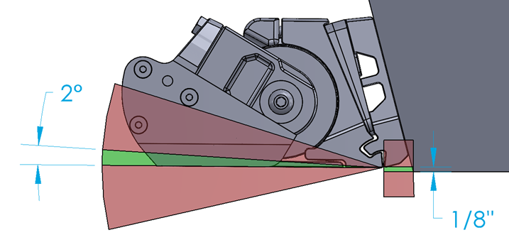
The Wedge Pack Assembly (Items 4, 5, 6, 7, and 8 in Inventory Parts) allows for the adjustment of the Controllers to the boat’s transom angle. The figure below illustrates the differences in the angle between the aft end of the running surface and the transom (A) and the resulting effects on Wedge Pack selection (B). The top two images show correct angle adjustments. The bottom two images show incorrect angle adjustments.
For optimal performance, the Seal Plate must be completely flush with the aft end of the running surface of the boat, which will eliminate angle C in the figure above. The Seal Plate can angle upward up to 2 degrees with a negligible effect on system performance. DO NOT mount the Controller angled upward more than 2 degrees. DO NOT mount the Controller angled downward at all.
6.1 Measurement Steps
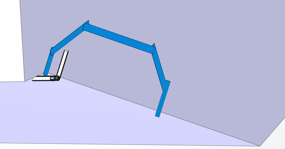
- Using the selected Controller locations from Section 5, measure the angle with a digital protractor from the running surface to the transom, perpendicular to the deadrise. See the figure below for an example of the measurement on the port Controller, outboard location.
- Measure the inboard and outboard ends of the port 1 Controller area and use the larger angle in the following Sections. Round up to the nearest degree.
- Measure inboard and outboard ends of the starboard Controller area and use the larger angle in the following Sections. Round up to the nearest degree. As with every step, repeat measurement process for both port and starboard sides. Note: It is possible to find different angles between port and starboard side of the hull.
- For four (4) Controller systems:
- Measure the inboard and outboard ends of the port 2 Controller area and use the larger angle in the following Sections. Round up to the nearest degree. Note: It is possible to find different angles between port 1 and port 2 locations.
- Measure the inboard and outboard ends of the starboard 2 Controller area and use the larger angle in the following Sections. Round up to the nearest degree. Note: It is possible to find different angles between starboard 1 and starboard 2 locations.
5. Determine the number of Wedge Plates required for each Controller’s Wedge Pack using the transom angle measured previously and Table 3.

The transom and Wedge angles indicated in the Table 3 are the maximum range of the product. If the boat’s transom angle is outside the range of Table 3, do not add or remove more Wedges to accommodate the different angle. Contact Seakeeper to determine the best course of action.
Table 3 – Transom Angle and Wedge Plates
| TRANSOM ANGLE | 3 DEGREE | 4 DEGREE | 5 DEGREE | Top Bolt | Bottom Bolt |
| 90 | 3 | 1 | 2 | 75 MM BOLT LENGTH | 40 MM BOLT LENGTH |
| 91 | 3 | 2 | 1 | ||
| 92 | 1 | 2 | 2 | ||
| 93 | 2 | 1 | 2 | ||
| 94 | 3 | 2 | |||
| 95 | 3 | 1 | 1 | ||
| 96 | 1 | 1 | 2 | ||
| 97 | 2 | 2 | |||
| 98 | 2 | 1 | 1 | ||
| 99 | 2 | 2 | |||
| 100 | 1 | 2 | |||
| 101 | 1 | 1 | 1 | 55 MM BOLT LENGTH | 35 MM BOLT LENGTH |
| 102 | 2 | 1 | |||
| 103 | 2 | 1 | |||
| 104 | 3 | ||||
| 105 | 1 | 1 | |||
| 106 | 1 | 1 | |||
| 107 | 2 | ||||
| 108 | 1 | ||||
| 109 | 1 | ||||
| 110 | 1 |
6.2 Hulls with Unique Stern Features
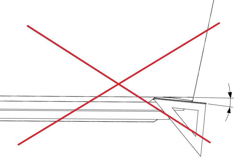
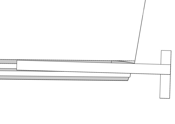
For many planing hulls, the aft portion of the running surface is straight, however, there can be exceptions where there is a curvature, angle, or twist just forward of the transom. This may be referred to as a stern wedge, hook, or rocker. These types of features are generally added to the hull to improve handling characteristics or induce a constant trim, adding a bow down moment during normal running conditions.
Be sure to use a 3-ft (0.9 m) straight edge along the hull bottom when evaluating the transom angles to obtain a correct assessment of the running surface.
If the Seal Plate were to be installed following the same angle as a stern wedge, it would create a permanent additional upward force in the aft of the boat, and the bow would be pushed down irreversibly. This incorrect assessment for installation is demonstrated below.
Measure the angle of the transom over a greater length of the running surface up to 3-ft (0.9 m) to ensure the proper angle.
6.3 Wedge Pack Angle Adjustment
For Seakeeper Ride 750-1500, the Wedge Pack angle can be adjusted after installation. Proper care must be taken during the initial installation procedure to make adjustment as smooth as possible.
Notes for Initial Installation
- Adhesive may seep into the cavities of the Wedge Pack during installation, which will make removal of the Actuator Plate and Wedge Plates difficult. Before adhering, place masking tape on the inside of the oval holes. While mounting, clean adhesive from the oval holes and as much of the other holes and gaps as possible.
- The Wedge Pack angle options are split into two halves based on bolt length. See Table 3. Once the Transom Plate is adhered to the boat, the bolts cannot be changed, meaning only Wedge Pack angle options corresponding the bolt lengths present will be available.
Wedge Pack Angle Adjustment
Reverse the steps in Section 12.1 or 12.2 of the Mechanical Installation Manual (750-1500) to remove all components aft of the Wedge Pack. The Wedge Pack bolts can then be loosened to adjust the Wedge Plates selection. See detailed steps below:
Note: Bolt count and images are for 750 Quad Controllers, and will vary slightly depending on Controller size.
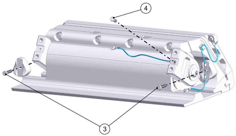
- Remove the two (2) M5-0.8 x16 Hex Head Screws holding the Blade Anode in place.
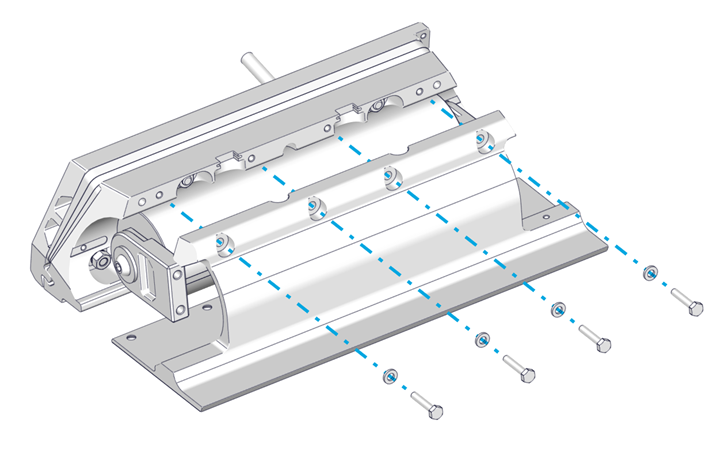
- Remove the four (4) M8-1.25 x 20 mm Hex bolts holding the Blade in place, and set the Blade aside.
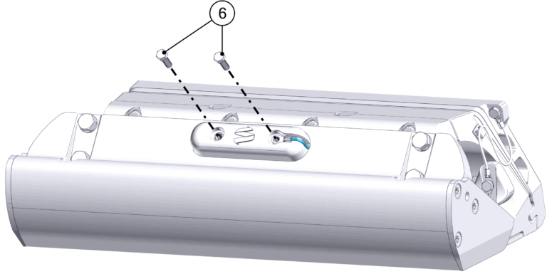
- Remove the five (5) M5 Hex Head Screws holding the bonding wires and Actuator Plate Anodes.
- If Concealed Actuator Cable routing is present, loosen the Cable Gland from the inside of the boat to allow the Actuator cable to move freely once the Seal Plate is removed. If Exposed Actuator Cable routing is present, remove the two (2) Phillips Screws holding the Cable Guide Support in place.
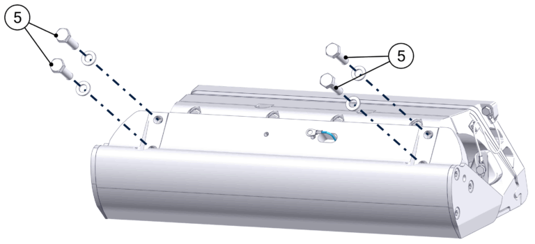
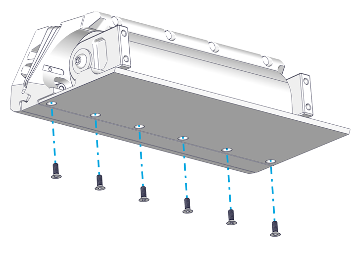
- Loosen the top four (4) M6-1.0 x 30 mm Hex Head Bolts. Remove the bottom six (6) M6-1.0 x 16 mm Torx Flathead Screws. Remove the top four (4) M6-1.0 x 30 mm Hex Head Bolts, which will allow the Seal Plate and Actuator to be removed. Gently pull the Actuator Cable out far enough for Wedge Pack adjustment. Support the Actuator.

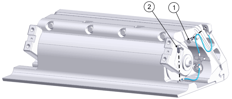
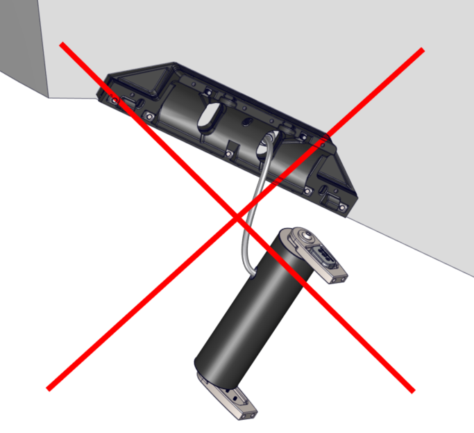
ATTENTION: Once the Seal Plate is removed, the Actuator will be unsupported. DO NOT allow the Actuator to hang by the cable. Use a table, strap, or some other method to support the weight of the Actuator.
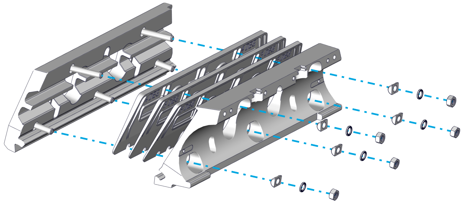
- Remove the five (5) M8 Nuts, Wedge Lock Washers, and Cylindrical Washers holding the Actuator Plate and Wedge Plates.
- Remove the Actuator Plate and switch Wedge Plates as needed.
- Adhesive may have seeped into cavities of the components during initial installation, which will cause them to hold in place even after the M8 Nuts are removed. A rubber mallet or another non-marring tool may be used to gently break away the components from the small amount of adhesive.
- For Concealed Cable Routing: Older versions of the Wedge Plates do not have openings in the bottom of the oval holes to allow the Wedge Plates to be removed past the Actuator Cable. This will require the Actuator Cable to be completely removed. Follow the initial steps in the Actuator Replacement guide to unpin and remove the Actuator Cable.
- Reassemble the Wedge Pack with the altered Wedge Plate combination and the Actuator Plate. Attach using the five (5) Cylindrical Washers, Wedge Lock Washers, and M8 Nuts, in that order. Torque to 130 in-lbs (14.7 N-m).
- Follow the steps in Section 12.1 or 12.2 of the Mechanical Installation Manual (750-1500, 375A and 525A) in order to re-install the Controller components.
- Apply additional threadlocker if the original threadlocker has worn off (Vibra-Tite VC-3 recommended).
- Remember to reinstall bonding wires and Anodes.
- Note torque values:
- Anode Screws – 25 in-lbs (2.8 N-m)
- Seal Plate bottom bolts – 80 in-lbs (9.0 N-m)
- Seal Plate top bolts – 50 in-lbs (5.6 N-m)
- Blade Bolts – 130 in-lbs (14.7 N-m)