Mechanical Installation Manual (750-1500, 375A and 525A)
5.3 Beam-Wise Location
There are several hull features that should be considered when determining the location of the Controllers in a beam-wise orientation.
As a general rule, the Controllers must be mounted as far outboard as possible, up to the chines (if the hull has chines). Details on the precise beam wise location is in the following sections.
When installing a four (4) controller system including 900, 1125, 1275 & 1500 installing the larger controller outboard (example 900 system uses a 525 mm span outboard and 375 mm span inboard) for roll restoring leverage.
Inboard Controllers should be mounted according to different priorities and should follow Section 5.4.

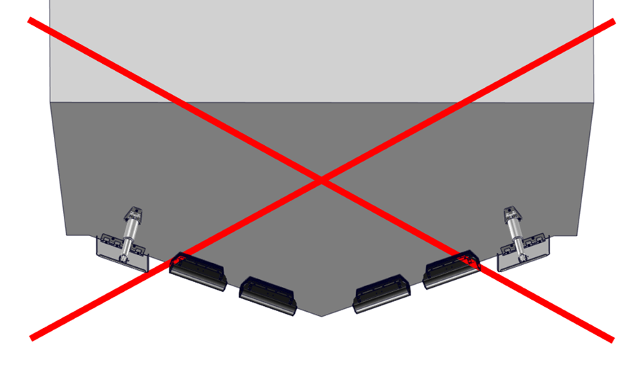
ATTENTION: Mounting the Controllers towards the centerline of the boat reduces the leverage the system has on the boat and severely reduces roll performance.
Chines
Note: In this instruction manual the term ‘Chine’ is regarding the intersection of the hull bottom and hull side with an abrupt change in deadrise angle. This is sometimes referred to as ‘Reverse Chine’.
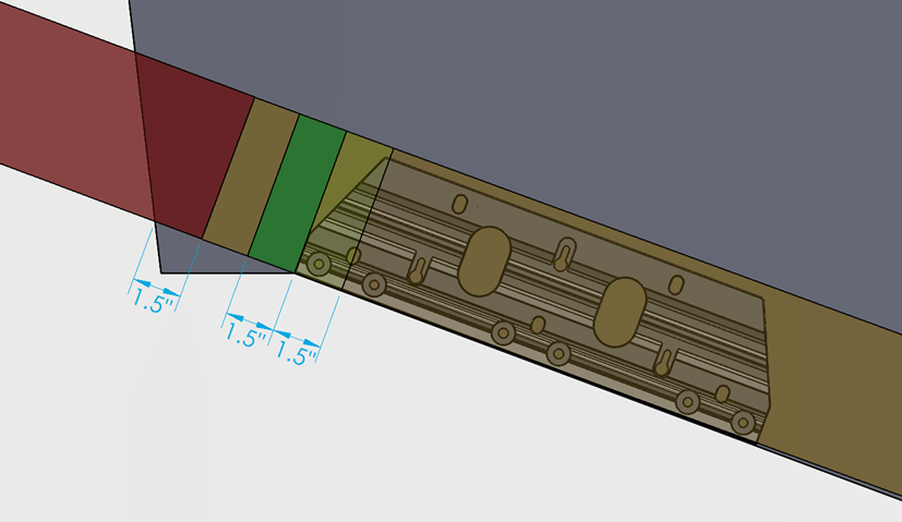
Based on the considerations of engine spacing and transom appendages, some installations will require the Controllers to extend outboard of the inboard edge of the chine. An overlap of the outboard chine of 1.5 in. (38 mm) is acceptable. For overlaps greater than 1.5 in. (38 mm), performance may degrade rapidly. The figure below illustrates placement of the outboard edge of the Controller with the following color code:
- Green (Outboard of chine up to 1.5 in. (38 mm)) – Ideal
- Yellow (Inboard of chine up to 1.5 in. (38 mm)) – Good
- Orange (More than 1.5 in. (38 mm) from chine) – Acceptable*
- Red (Overhanging Hull Side) – Unacceptable
*Controllers must NOT be mounted far enough inboard to reduce leverage, as outlined above.
Hull Side Spacing
It is possible to have an installation where the Controller is mounted too far outboard causing water flowing around the hull side to interfere with the Controller and substantially reduce performance.
As a general rule, the Controller should be mounted at least 1.5 in. (38 mm) inboard of the hull side, as shown below. In some instances where the transom is not completely transverse (example: a sportfish with curved transom), verify the Controller and Blade does not extend beyond the hull side prior to installation.
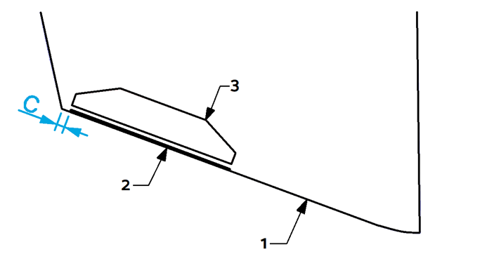
Figure 23 – Hull Side Clearance
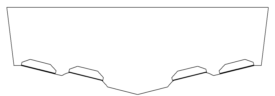
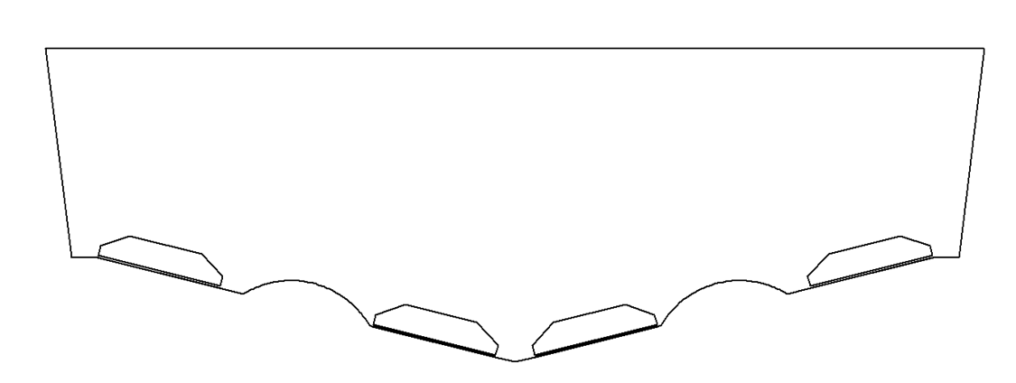
Propeller Tunnels
In the event a hull has propeller tunnels and there is not enough beam to install a two (2) Controller system outboard of the tunnel, it is possible to utilize a four (4) Controller system.
The outboard Controllers should be mounted outboard of the propeller tunnel.
The inboard Controllers could be mounted in two locations. The inboard Controllers can be mounted on top of the propeller tunnel if there is a straight section of the tunnel to match with the Controller Seal Plate. Alternatively, the inboard Controllers can be mounted on the deadrise inboard of the propeller tunnel.
Review of other hull features like convex and concave hull bottoms and variable deadrise should be considered with this placement.
Catamarans
When mounting on a catamaran, all general guidelines from other sections in this manual will still apply.
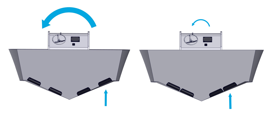
Outboard Controller – The outboard Controller should be mounted as far outboard as possible, up to the chine, which results in mounting on the outboard deadrise of each demihull as shown below. The outboard Controller should be the larger of the two Controllers. When installing a four (4) controller system including 900, 1125, 1275 & 1500 installing the larger controller outboard (example 900 system uses a 525 mm span outboard and 375 mm span inboard) for roll restoring leverage.
Inboard Controller – The inboard Controller can be mounted on either the inboard or outboard deadrise of each demihull (inboard and outboard deadrise mounting shown below) depending on available space, transom characteristics, engine location, etc. The inboard Controller should be mounted as far outboard as possible without contacting the outboard Controller.
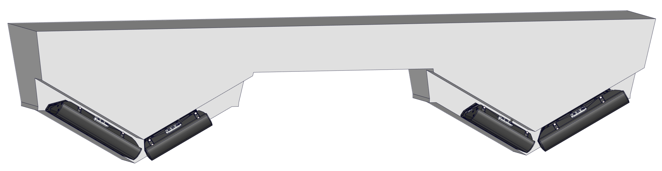
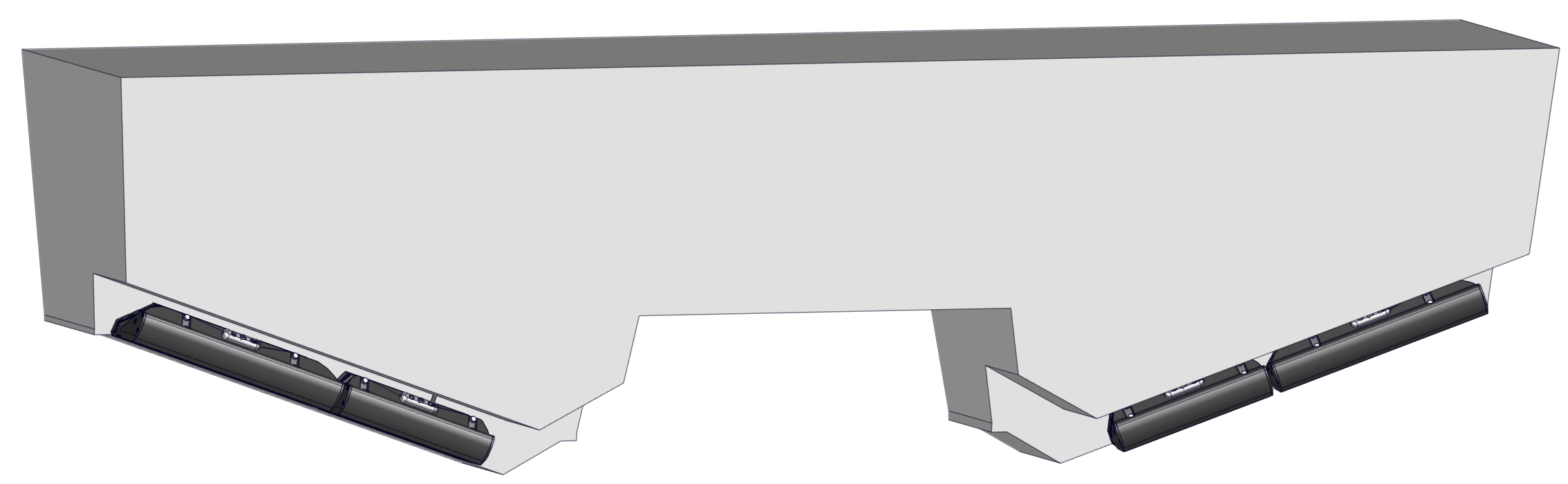
Due to the generally smaller beam-wise space when compared to a monohull, catamarans will often result in Seakeeper Ride being mounted very close to the engines. The installer must ensure that the engines will not physically contact the Controllers when fully trimmed down AND turned fully to the side. Possible solutions if the Controllers will make contact include setting back the engines on a bracket or recessing the Controllers in the hull by creating a pocket or shelf.
See Engine Spacing (Section 5.4). Catamaran installations will also often result in the Controllers being forward of the propellers. As described above, many successful installations have been completed with large amounts of propeller overlap.