Seakeeper 40 Installation Manual (90715-3) 40-244-0121 to 40-254-0199
4.2 Installation Considerations
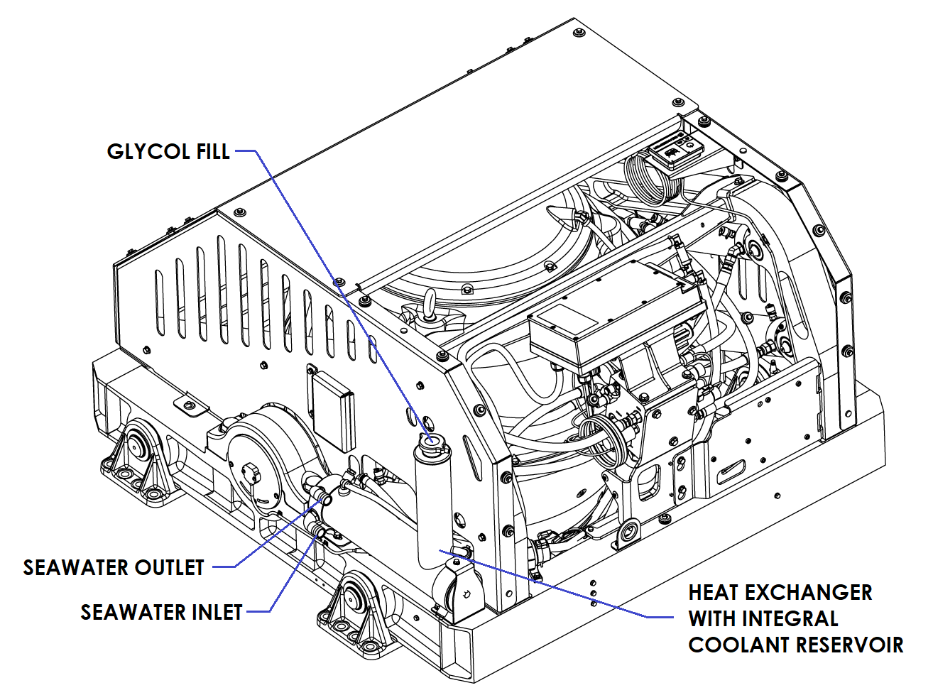
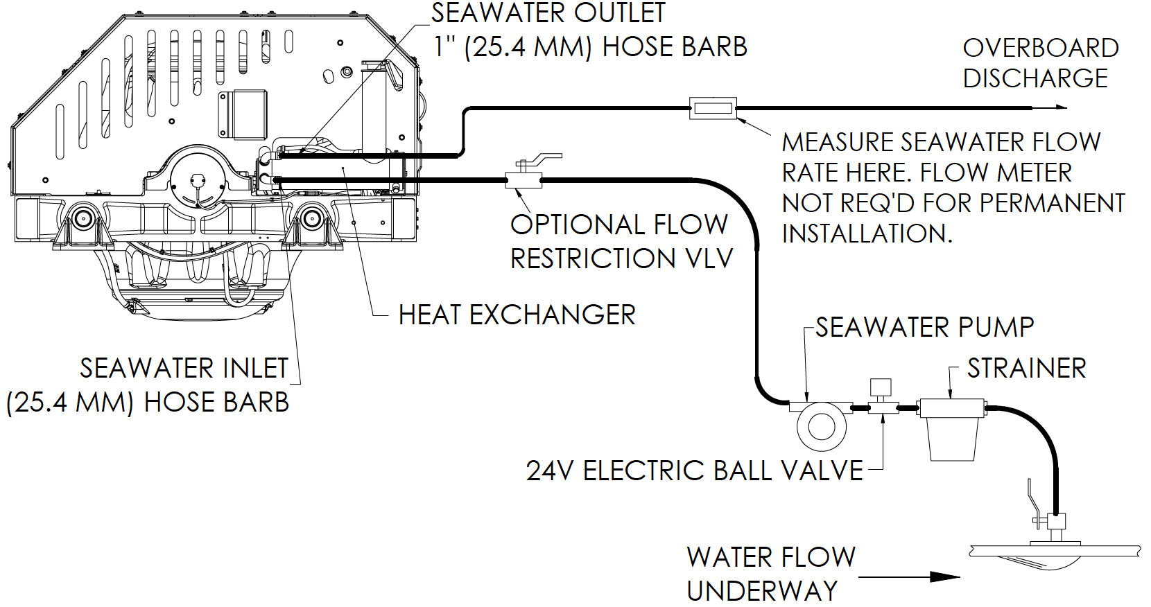
- Installer is responsible for supplying a dedicated seawater pump, motorized ball valve, and associated plumbing. Seawater connections on the heat exchanger mate with 1 in. (25.4 mm) hose. An optional seawater pump and ball valve assembly can be purchased through Seakeeper (P/N 30628).
- Unintended seawater flow from the seawater pick-up during the vessel’s underway operation is unacceptable and may cause stress to internal components. Unintended flow should be mitigated through pump selection, using a diaphragm-style pump or an inlet control valve. Continuous cooling flow from shared through-hull plumbing, a centralized chiller, or a cooling system is unacceptable for on-demand Seakeeper models.
- There is no need to disconnect hose from glycol pump except to replace the pump. In this case, provision will need to be made to catch draining glycol as plumbing is disconnected. Use caution to avoid breaking plastic hose connections on pump casing.
- An output is available from the Seakeeper 40 wire harness to power and automatically control seawater pump and electric ball valve. This pump and valve must operate on 24 VDC and consume less than 20 A. Pumps requiring other voltages or higher current can still be controlled by using this supply from the wire harness to trigger an installer-supplied contactor, but a separate source of power must be provided.
- The seawater pump and ball valve are powered by Seawater Pump Output Cable, via “SW Pump 24 VDC Out” on the Seakeeper 40, as outlined in Electrical Installation section.
- A dedicated through-hull fitting should be installed for each Seakeeper unit onboard the vessel to ensure sufficient seawater flow to each unit.
- It is recommended the seawater pump be installed below the waterline, as close to baseline of the vessel as practically possible, to maintain positive inlet pressure on the pump in all operating conditions.
- A self-priming seawater pump may be required to maintain water flow in all underway conditions. Cavitation can occur at the seawater inlet and potentially cause an air-lock condition restricting seawater flow to the heat exchanger.
- Maximum seawater pressure in heat exchanger is 20 psi (1.4 bar).
- Seawater flow requirement through heat exchanger is 13 GPM (49.2 LPM) minimum and 15 GPM (56.8 LPM) maximum under all operating conditions of the boat. When sizing the seawater pump, the installer should factor in losses for raw water plumbing. In addition to initial operation at the dock, new Seakeeper installations should be checked to be within the flow requirements while the vessel is at speed. Flows above 15 GPM (56.8 LPM) could affect heat exchanger life.
- Vented loops are optional and should only be considered with centrifugal style pumps. Self-priming or positive displacement style pumps do not require a vented loop, including Seakeeper supplied optional pump (P/N 30628).