Seakeeper 1 Installation Manual (90519-2) 1-233-0631 to Current
2.0 Mechanical Installation
2.1 Mechanical Installation Introduction
The Seakeeper 1 can produce forces of up to 1,515 lbs (6.74 kN) in the vertical direction, 2,248 lbs (10.0 kN) in the longitudinal direction, and 1,697 lbs (7.55 kN) in the lateral direction at each of the four mounts. Careful consideration should be given to foundation design to ensure it can safely transfer these loads into the hull. These loads represent a worst-case operating condition that includes a 6 G acceleration evaluated in each direction independently. The responsible party for designing the supporting structure (boat builder, installer, or hired sub-contractor) must accommodate the above forces plus a reasonable safety factor. Seakeeper recommends a minimum safety factor of 2.0 (resulting in a safety margin of 1.0).
It is assumed that the installer is familiar with mounting using mechanical fasteners to marine structures and has performed structural analysis to ensure the structure to which the Seakeeper mounts can properly transfer the loads the Seakeeper creates into the hull structure. If the installer has any doubt about the ability of the structure to transfer the loads to the hull, then a licensed naval architect or marine engineer should be contacted to do a structural analysis.
The installer should review the following list of reference drawings to ensure the mechanical installation procedure is fully understood.
Reference Documents & Drawings
2.2 Selection of Seakeeper Installation Location
2.2.1 Location Considerations
Selection of mounting location of the Seakeeper should consider the following desirable features:
The Seakeeper should be installed aft of amidships to minimize high acceleration loadings due to hull / wave impacts during operation at high speed or in large waves. If the only possible installation location is forward of amidships, then the installer should have Seakeeper review the installation location prior to finalizing the design.
- Top-down access or sufficient clearance for access and removal of the Seakeeper 1 cover is required. For reference, see Drawing No. 90516—Seakeeper 1 Bolt-In Installation Details and Drawing No. 90514—Seakeeper 1 Bolt-In Clearances.
- Provide adequate clearance for all recommended scheduled maintenance and any necessary repairs, as shown in Figure 4 and Drawing No. 90516—Seakeeper 1 Bolt-In Installation Details.
- Access for the removal and re-installation of the Seakeeper 1 should be considered.
- The Seakeeper should be installed in a dry space to minimize the effects of corrosion. If installed and exposed to weather, use the deck cover enclosure (P/N 90628).
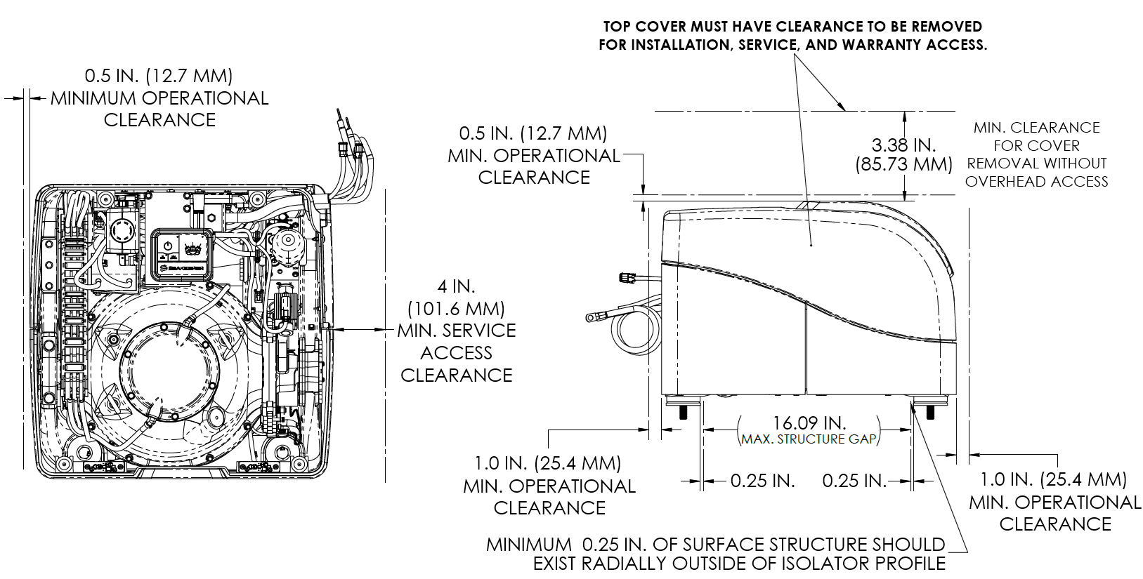
Figure 4 – Seakeeper 1 Service and Operating Clearances (Drawing No. 90516)
Note: Adequate access to remove the Seakeeper 1 cover must be incorporated into the installation design to allow for regular maintenance, service, and repair of components.
2.2.2 Noise and Soundproofing
Seakeeper noise has been measured under steady-state conditions (no wave load) in Seakeeper‘s Engineering Lab and in our Factory Demo Boat. The steady-state noise at 1 meter is typically less than 64 dBC. As the frequencies emitting the highest sound pressures are low (like other marine machinery), it is recommended that the Seakeeper be installed in an enclosed space such as a leaning post/seat, bilge, center console, or machinery space.
2.3 Mechanical Installation
Reference Documents & Drawings:
- 90514 – Seakeeper 1 Bolt-In Clearances
- 90516 – Seakeeper 1 Bolt-In Installation Details
- 90517 – Seakeeper 1 Installation Fixture Kit
- 90559 – Seakeeper 1 Generic Installation Guide
- 90599 – Seakeeper 1 Bolt-In Kit
- 90564-4 – Seakeeper 1 Installation Plate
- 90692-1 – Seakeeper 1 Deck Enclosure Installation Instructions
2.3.1 Preparation of Vessel Structure
Drawing No. 90559 – Seakeeper 1 Generic Installation Guide shows various structural arrangements to support the integration of the Seakeeper 1. The Generic Installation Guide offers above and below-deck installation arrangements with fiber-reinforced plastic (FRP) and aluminum structures, which should provide solutions for most vessels. Depending on the structure to which the Seakeeper is fastened, blind threaded holes or through-bolting can be utilized. The Seakeeper 1 is affixed to the hull via four bolts in the Seakeeper 1 frame. Each Seakeeper 1 foundation bolt has a vibration isolation assembly to minimize the transmission of vibrations to the hull structure.
Refer to Seakeeper Drawing No. 90516 – Seakeeper 1 Bolt-In Installation Details. This drawing contains critical design dimensions and loads that must be considered in the design of the boat’s structure that will receive the Seakeeper 1. It is assumed that a proper structural analysis has been performed for the vessel structure to which the Seakeeper will be fastened to ensure proper strength margins for the loads the Seakeeper will create during operation.
The vessel structure supporting the Seakeeper should be installed so the Seakeeper is parallel to the waterline in the transverse direction and within 2 degrees longitudinally.
In addition, the four areas on top of the structure on which the Seakeeper 1 will rest need to be co-planar within .06 in. (1.5 mm) to minimize potential distortion of Seakeeper isolation mounts when installed.
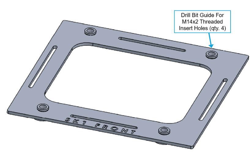
Seakeeper offers an installation fixture kit, P/N 90517. The fixture has four (4) holes at the same centers as the mounting holes on the Seakeeper 1. It locates the hole patterns at the proper spacing in the forward-aft direction and the port-starboard direction. See Figure 5 for more details regarding the Seakeeper 1 template.
Note: Do NOT use the installation fixture to establish the Seakeeper envelope dimensions or clearances. For envelope dimensions, refer to Drawing No. 90516—Seakeeper 1 Bolt-In Installation Guide. A 3-D model of Seakeeper 1 is available on the Seakeeper website, www.seakeeper.com, to aid in designing the Seakeeper foundation and the space around it.
2.3.2 Transfer of Holes to Boat Structure
The following instructions should be used to establish the Seakeeper 1 bolt pattern on the hull structure designed to accept the Seakeeper 1, based on the information provided in Drawing No. 90599—Seakeeper 1 Bolt-In Kit and Drawing No. 90516—Seakeeper 1 Bolt-In Installation Details.
- Lower installation fixture onto vessel structure.
- The four Isolation Mounts, where the Seakeeper 1 contacts the hull structure, must be coplanar to within 0.06 in. (1.5 mm).
- Align fixture in desired location and transfer holes from fixture plate to the vessel structure by transfer punch. Note that holes in fixture plate are ø 9/16 in. (14.287 mm).
- Using the bushings in the fixture holes as a guide to stay perpendicular with the vessel structure, drill 4 X 9/16 in. diameter holes for M14-2.0 (21 mm length minimum) threaded inserts in vessel structure at marked locations to mate with holes in the Seakeeper foundation.
- Tap threads in holes for M14 x 2.0, 1.5 x diameter threaded inserts.
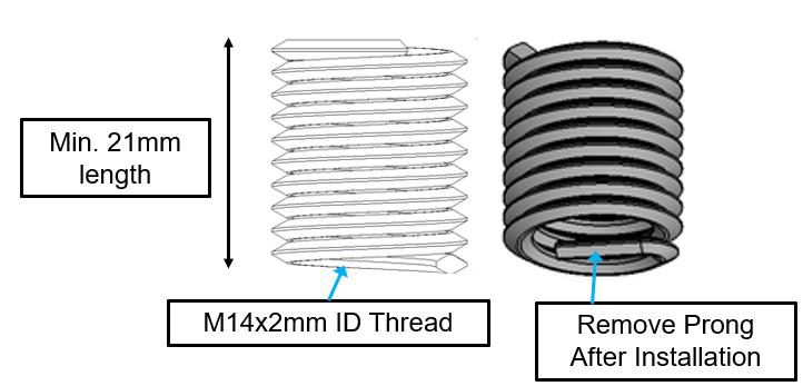
- Install threaded inserts into holes using Helicoil installation tool.
- Remove threaded insert prongs after threaded inserts are installed.
2.3.3 Installation of Seakeeper
- Locate and position the lower snubbing washers onto the vessel foundation structure at the four (4) hole locations.
- NOTE: Sealant or caulk should be applied around the outside edge of the lower face of each lower snubbing washer where it contacts the vessel structure. This will maintain the washer’s position and prevent water from wicking between the parts and causing corrosion.
- Sealant is not required between the snubbing washer faces and isolator bushings.
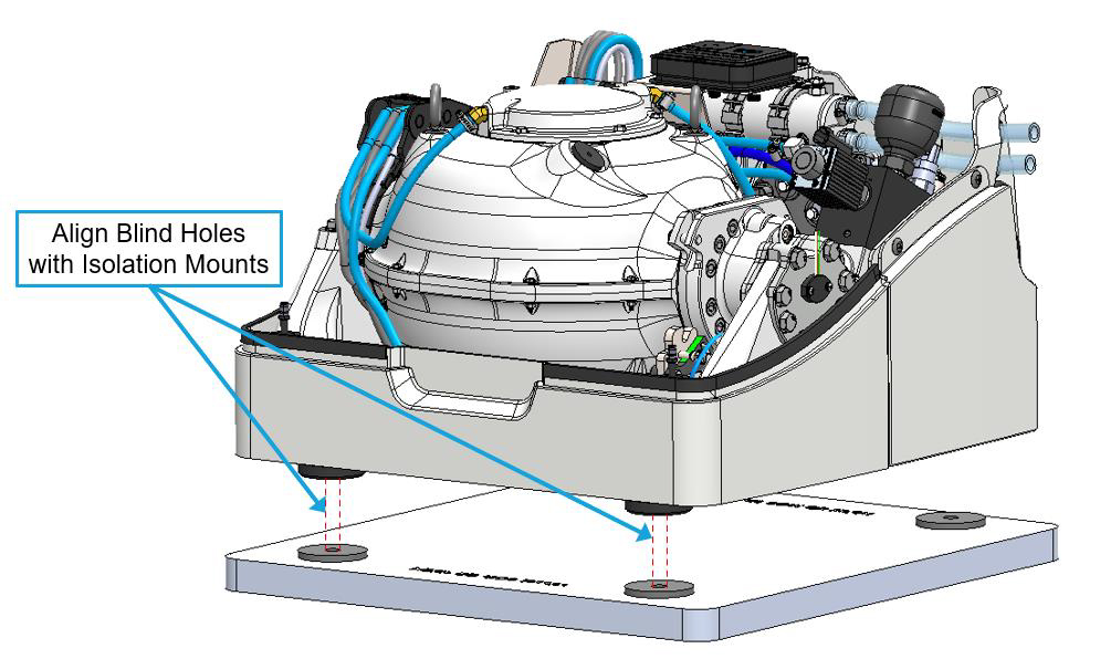
- Lower the Seakeeper 1 onto the lower snubbing washer on the vessel structure and align over drilled holes.
- Using a flexible extendable magnet (McMaster P/N: 3838A42 or similar), install the Seakeeper 1 Bolt-In Kit (P/N 90599): the isolation mount sleeve tube, upper snubbing washer, wedge-lock washer, and bolt at each isolation mount.
- Figure 8 shows an exploded view of the Bolt-In Kit.
- Before installation, apply a moderate coat of anti-seize to the threads of each bolt.
- By attaching the magnet to the upper snubbing washer, wedge-lock washer, and M14 Bolt, they can be stacked as one assembly.
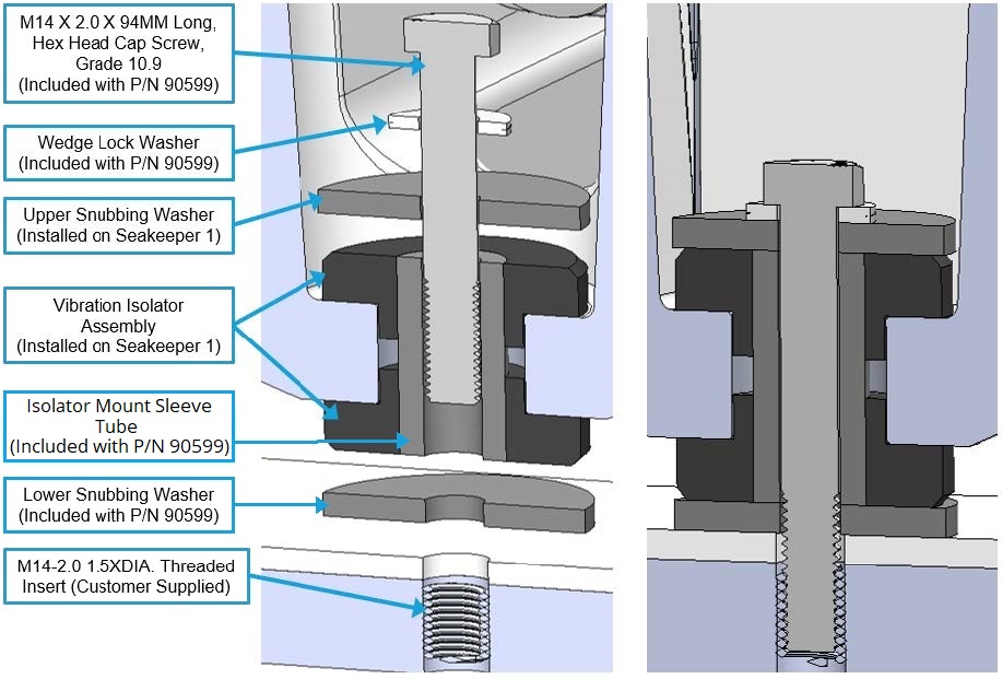
Figure 8 – Seakeeper 1 Bolt Stack Arrangement Cutaway –
Exploded (left) / Installed (right) (P/N 90599)
- Torque all fasteners to 115 ft-lbs (156 N-m). New bolts must be used for each installation and re-installation.
- Threaded inserts can be reused if they are intact and without damage.
- Proceed to the electrical and cooling portion of the installation.