Seakeeper 1 Installation Manual (90519-2) 1-233-0631 to Current
1.0 Introduction
Seakeeper 1
Installation Manual
90519, Rev 2

This document is intended to give details and guidance for a boat builder or equipment installer to properly install the Seakeeper 1 (applicable to serial numbers 1-233-0631 to current).
Reference Documents:
Precautions
- The Seakeeper must only be lifted from the supplied lifting eyes (see Section: Transport and Unpacking).
- Precision bearings support the Seakeeper flywheel. While unpacking and lifting the Seakeeper assembly, DO NOT drop or impart mechanical shock, as this could damage the bearings.
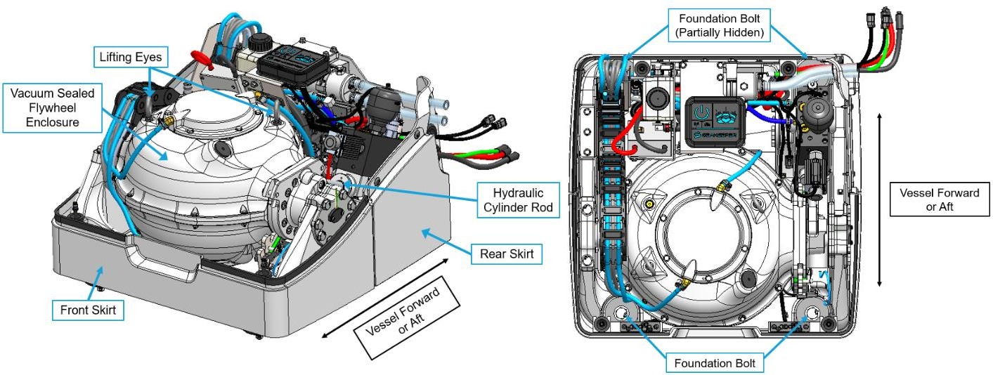
- While handling or installing the Seakeeper assembly, protect exposed hydraulic brake cylinder rods (see Figure 1) from scratches or damage, as this could lead to premature seal failure and oil leaks.
- Exercise care to protect any exposed surfaces, as damage to the finish could lead to the Seakeeper‘s early appearance degradation.
Safety

There is a large torque about the gimbal axis when the Seakeeper is precessing. Seakeeper cover panels are provided to prevent personnel or equipment from contacting the Seakeeper while it is in operation. These covers should not be stepped on or have anything placed on top. The covers should always be in place during operation.
_________________________________________________________________________________________
If it is ever necessary to access the Seakeeper while the flywheel is spinning, the Seakeeper must be locked at the display to stop the Seakeeper from precessing.
_________________________________________________________________________________________
Stand clear of the Seakeeper and all moving components during operation.
_________________________________________________________________________________________
Unit may be started remotely. Assume it could move without warning.
_________________________________________________________________________________________
The following must be true before accessing the Seakeeper:
• Input power must be disconnected for at least 10 minutes
• Seakeeper must be locked
• Flywheel must be at zero speed
Transport and Unpacking
Reference Documents:
- 90515 – Seakeeper 1 Unpacking Instructions
- 90510 – Seakeeper 1 Hardware Scope of Supply
- 11766 – DC Seakeeper Lifting Bar Kit
Transport
- Use a Seakeeper-provided shipping crate for transport, P/N 12098. The overall dimensions of a fully-packed Seakeeper 1 crate are 27.5 L x 27.5 W x 23.25 H in. (0.70 L x 0.70 W x 0.60 H m) with a weight of 430 lbs (195 kg), including accessories.
- Seakeeper 1 crates can be stacked up to two (2) units high. Only like units should be stacked, i.e., Seakeeper 1 on top of a Seakeeper 1
- Both air and ground transport are acceptable and available through Seakeeper.
- Seakeeper shipping crates must be transported in environmental conditions between -4°F and 140°F (-20°C and 60°C).
Unpacking
Reference Drawing No. 90515 – Seakeeper 1 Crate Unpacking Instructions for detailed unpacking instructions. Once the Seakeeper 1 crate has been unpacked, follow these instructions when lifting the unit:
- Remove and set aside cover, electrical components, cables, and miscellaneous items.
- Attach the Small Gyro Lifting Bar Kit, P/N 11766, to the two lifting eyes on top of the Seakeeper enclosure.
- Stay clear of the Seakeeper 1 when it is being lifted, and follow safe practices for working under a suspended load. The Seakeeper 1 weighs 365 lbs (165 kg).
- Figure 2 shows the proper lifting arrangement. Drawing No. 90516 –Seakeeper 1 Bolt-In Installation Details provides additional details.
- Remove lifting eyes once the unit is installed. Lifting eyes must be removed prior to operation.
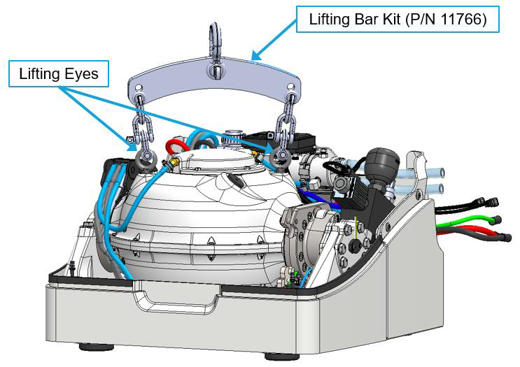
Figure 2 – Seakeeper 1 Lifting Arrangement