Mechanical Installation Manual (750, 750 Quad)
4. Inventory Parts
Please review all parts included before proceeding. The following figure and table describe all parts included in the assembly. Review parts and ensure all parts are present before starting the installation procedure.
Components shown are per Controller. Dual Actuator systems will have two (2) times the components listed, and Quad Actuator systems will have four (4) times the components listed.

- Blade
- Seal Plate
- Actuator
- Actuator Plate
- 3 Degree Wedge Plate
- 4 Degree Wedge Plate
- 5 Degree Wedge Plate
- Transom Plate
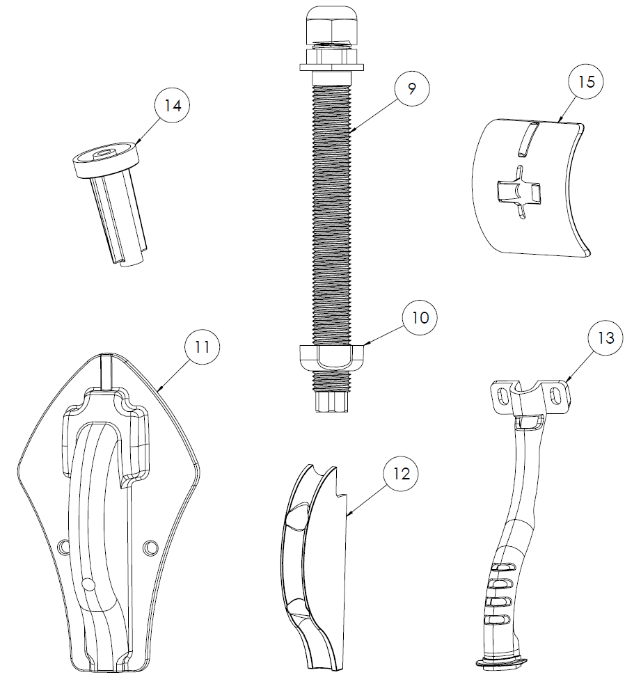
- Cable Gland Tube
- Cable Gland Nut
- Outer Cable Guide
- Inner Cable Guide
- Cable Support Guide
- Drill Guide Tube
- Drill Guide Follower
Hardware counts below are given in the format: x[QUAD ACTUATOR] / [DUAL ACTUATOR]
| Wedge Pack Hardware | Positioning Screws | |||
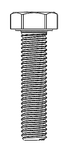 x3 / 5 M8-1.25 X 35 mm Hex Head Bolt | 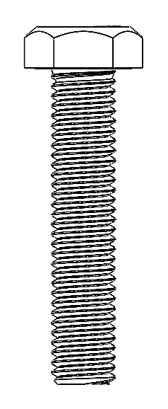 x3 / 5 M8-1.25 X 40 mm Hex Head Bolt | 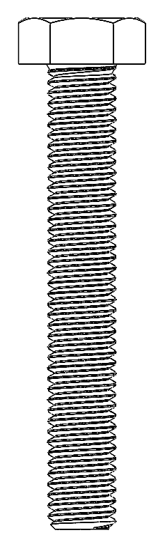 x2 / 4 M8-1.25 X 55 mm Hex Head Bolt | 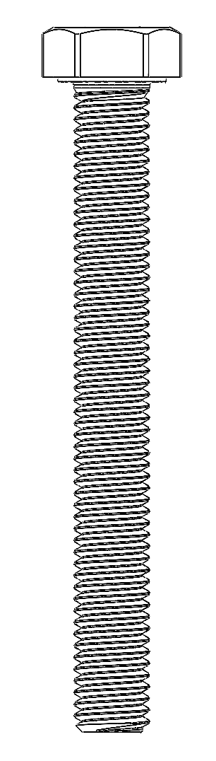 x2 / 4 M8-1.25 X 75 mm Hex Head Bolt |  x3 Phillips No. 8 x 1.25 in. Screw |
 x5 / 9 M8 Cylindrical Washer for Hex Head | x5 / 9 Transom Plate Bolt Cover | 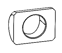 x5 / 9 M8 Cylindrical Washer | 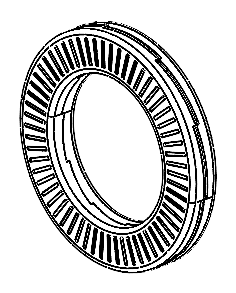 x5 / 9 M8 Wedgelock Washer |  x5 / 9 M8-1.25 Hex Nut |
| Seal Plate Hardware | Blade Hardware | |||
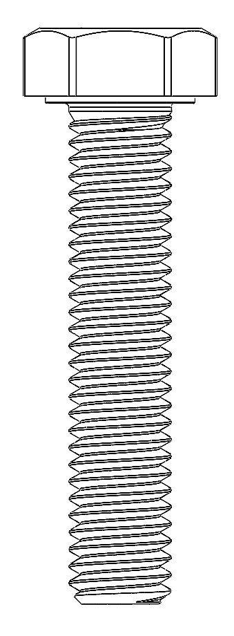 x4 / 6 M6-1.0 x 30 mm Hex Head Bolt |  x4 / 6 M6 Washer | 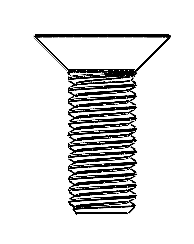 x6 / 10 M6-1.0 x 16 mm Flathead Screw | 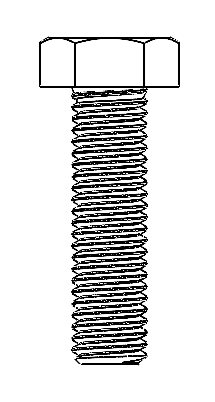 x4 M8-1.25 X 30 mm Hex Head Bolt |  x4 M8 Washer |
| Cable Routing Hardware | Endcaps | |||
 x2 Phillips No. 8 x 0.75 in. Screw |  x2 Phillips No. 8 x 1.5 in. Screw | 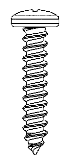 x2 Phillips No. 10 x 1.0 in. Screw |  x0 / 2 Endcaps (Only included with Dual Actuator systems) |
Note: Vibra-tite 122 threadlocker will also be included in the packaging.