Mechanical Installation Manual (750, 750 Quad)
5.2 Vertical Location
Seakeeper Ride’s Controllers must be mounted so that the bottom surface of the Seal Plate (Item Number 2 below) aligns flush and parallel with the hull bottom. The goal is to have the Seal Plate acting like an extension of the hull bottom. The Seal Plate’s location is determined by the Transom Plate (Item Number 8 below), which is affixed to the transom and adjusted up and down during installation to allow for fine-tuning the location.
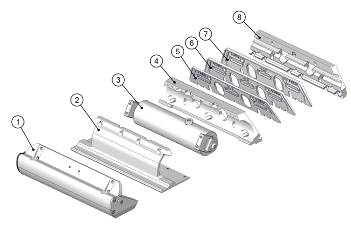
1) Blade
2) Seal Plate
3) Rotary Actuator
4) Actuator Plate
5) 5 Degree Wedge Plate
6) 4 Degree Wedge Plate
7) 3 Degree Wedge Plate
8) Transom Plate
Figure 8 – Seakeeper Ride 750 Controller Constituent Parts
The Ride Reference Line (RRL) is a guide for where the bottom of the Controller should be when mounted. The RRL is a representation of the bottom edge of the transom where it meets the running surface of the hull. Because of the unique shapes of different hulls, the RRL may not follow the bottom edge of the hull exactly. The following examples give guidance on where the RRL should lie on hull bottoms that are not perfectly straight.
An example transom with an exaggerated radius is shown below. The RRL is shown in blue and is the intersection of the two straight edges.
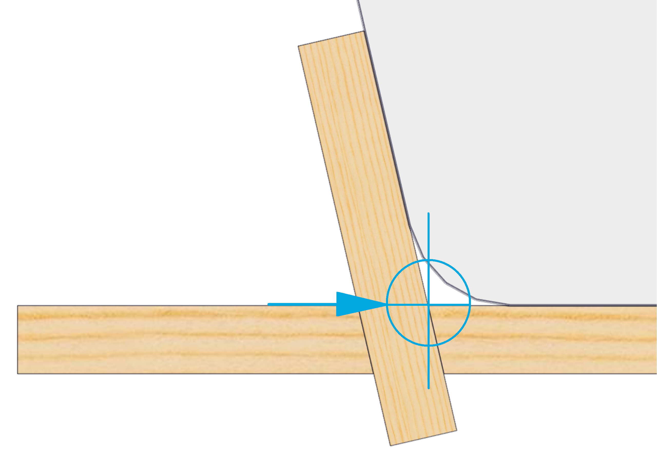
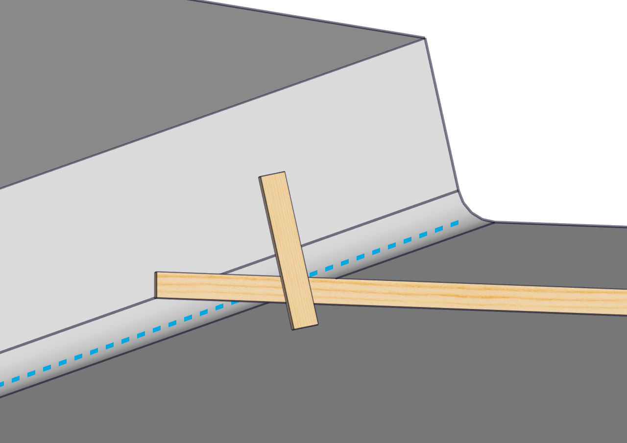
Figure 9 – Finding Reference Line with Straight Edges
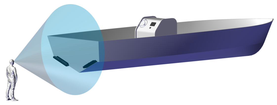
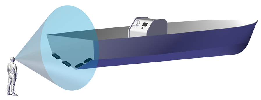
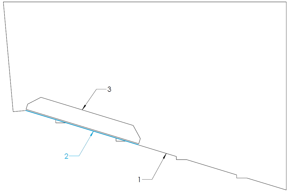
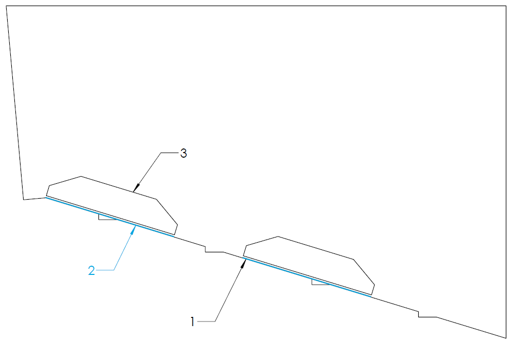
Figure 12 to Figure 19 in this section show a view from the stern of the vessel looking toward the bow. Label 1 indicates the bottom of the hull, Label 2 indicates the RRL, and Label 3 indicates the outline of the Transom Plate.
Strakes
Note: In this instruction manual the term ‘Strake’ is regarding a portion of the hull bottom which has an abrupt change in deadrise angle in comparison to the greater hull bottom. Sometimes referred to as ‘Lifting Strakes’ or ‘Spray Strakes’ it does NOT concern Chines.
For hulls with strakes, they can be ignored for the placement of the equipment and determination of the RRL. Strakes which extend all the way to the transom can reduce the authority of the Seakeeper Ride equipment. Terminating the strake at least 12 inches forward of Ride maintains full system authority.
Concave and Convex Deadrise
The Seal Plates (Item Number 2 in Figure 5) have a straight design. Some hulls may have curvature along the deadrise which will cause the Seal Plate to show gaps between the deadrise at either the ends or center of the plate. The following sections describe how to find the RRL in concave and convex deadrise hulls.
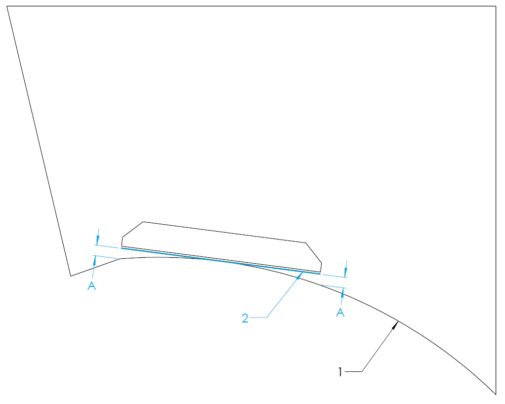
Concave Deadrise
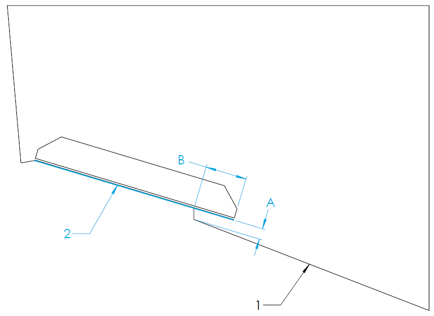
For vessels with concave curvature, the Seal Plate should be mounted such that the center of the Seal Plate is flush to the hull bottom and the ends of the Seal Plate are equidistant from the hull bottom (measurement A and B in the figures below). Measurement A and B must be 0.5 in. or less. More curvature decreases Seakeeper Ride Authority. For vessels with concave curvature, the RRL is defined as the tangent to the hull bottom, shown by the blue line.
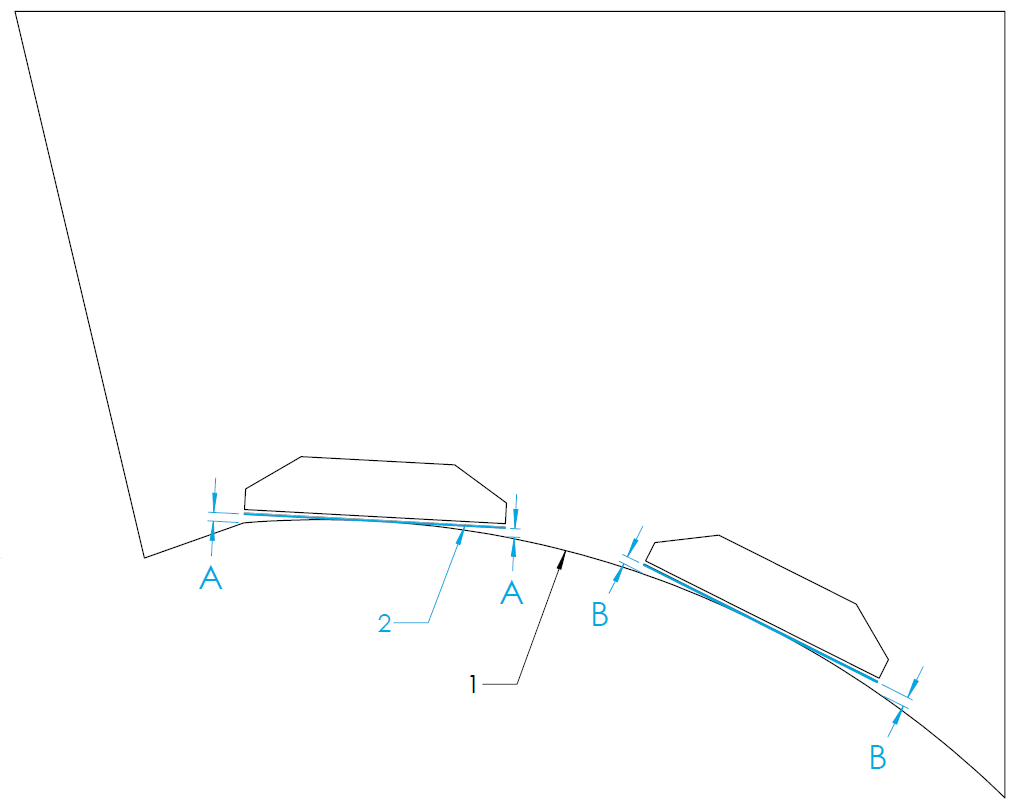
Convex Deadrise
For vessels with convex curvature, the ends of the Seal Plate should be mounted flush with the hull bottom with a gap between the center of the Seal Plate and the hull bottom (measurement A and B in the figures below). Measurement A and B must be 0.5 in. or less. More curvature decreases Seakeeper Ride Authority. For vessels with convex curvature, the RRL is defined as the straight line along the transom between inboard and outboard ends of the seal plate’s destination.
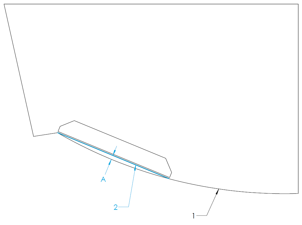
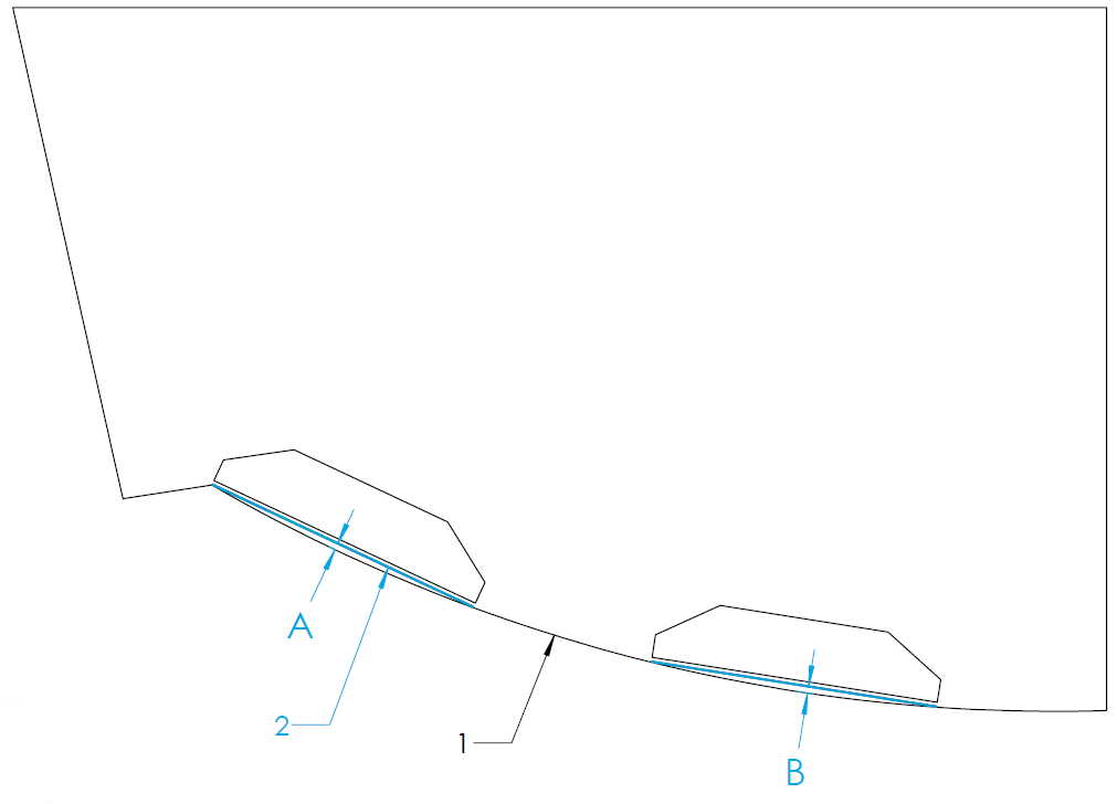
Figure 17 – Convex Hull Bottom RRL and Transom Plate Trace (Quad Controller)
Variable Deadrise
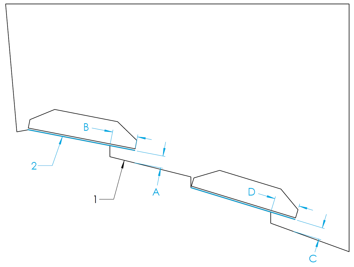
Variable deadrise hulls are those where the running surface has breaks that run longitudinally. Generally, these hulls have decreasing deadrise angle in each successive panel moving outboard from centerline. Seakeeper Ride Controllers are capable of being mounted on variable deadrise hulls, so long as the following mounting conditions can be met:
- Distance from inboard edge of the Controller to the running surface of the hull (Dimension A and C in the figures below) is 0.75 in. (19 mm) or less. This requirement only applies to vertical changes beneath the Controller.
- The portion of the Controller extending inboard of the deadrise break (Dimension B and D in the figures below) is 3 in. (76 mm) or less. For Quad Controllers, the overhanging portion of both Controllers added together must be 3 in. (76 mm) or less (In the figure below, B + D = 3 in. max).
In hulls with a variable deadrise, the RRL is the highest portion of the deadrise that the Seakeeper Ride system will cover. See the figure below for this position. Because performance may degrade rapidly if these conditions are not met, please reach out to Seakeeper for guidance in this instance if a boat falls outside these parameters.