Mechanical Installation Manual (750-1500)
6.3 Wedge Pack Angle Adjustment
For Seakeeper Ride 750-1500, the Wedge Pack angle can be adjusted after installation. Proper care must be taken during the initial installation procedure to make adjustment as smooth as possible.
Notes for Initial Installation
- Adhesive may seep into the cavities of the Wedge Pack during installation, which will make removal of the Actuator Plate and Wedge Plates difficult. Before adhering, place masking tape on the inside of the oval holes. While mounting, clean adhesive from the oval holes and as much of the other holes and gaps as possible.
- The Wedge Pack angle options are split into two halves based on bolt length. See Table 3. Once the Transom Plate is adhered to the boat, the bolts cannot be changed, meaning only Wedge Pack angle options corresponding the the bolt lengths present will be available.
Wedge Pack Angle Adjustment
Reverse the steps in Section 12.1 or 12.2 of the Mechanical Installation Manual (750-1500) to remove all components aft of the Wedge Pack. The Wedge Pack bolts can then be loosened to adjust the Wedge Plates selection. See detailed steps below:
Note: Bolt count and images are for 750 Quad Controllers, and will vary slightly depending on Controller size.
- Remove the two (2) M5-0.8 x16 Hex Head Screws holding the Blade Anode in place.
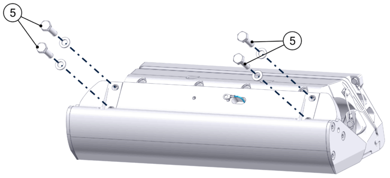
- Remove the four (4) M8-1.25 x 20 mm Hex bolts holding the Blade in place, and set the Blade aside.
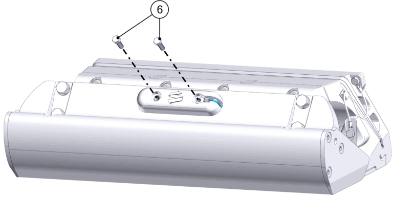
- Remove the five (5) M5 Hex Head Screws holding the bonding wires and Actuator Plate Anodes.
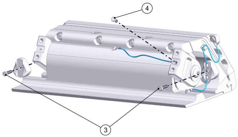
- If Concealed Actuator Cable routing is present, loosen the Cable Gland from the inside of the boat to allow the Actuator cable to move freely once the Seal Plate is removed. If Exposed Acutator Cable routing is present, remove the two (2) Phillips Screws holding the Cable Guide Support in place.
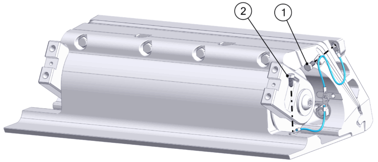
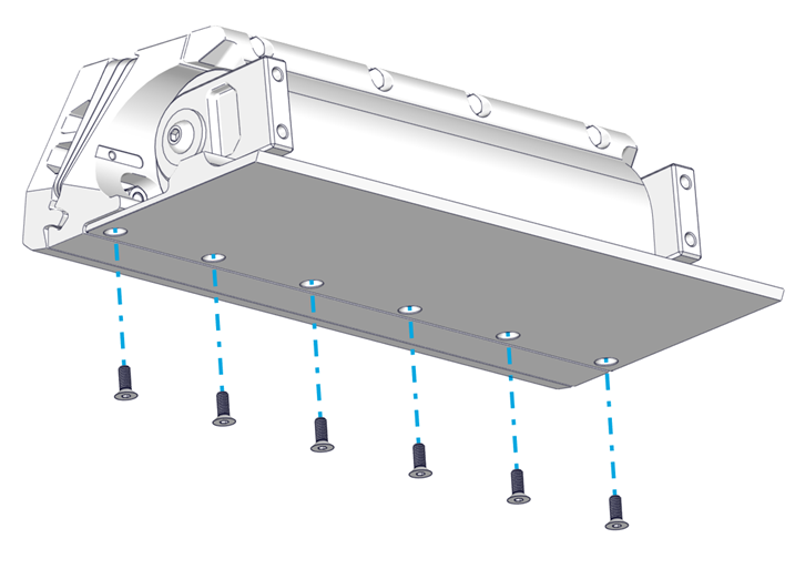
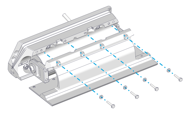
- Loosen the top four (4) M6-1.0 x 30 mm Hex Head Bolts. Remove the bottom six (6) M6-1.0 x 16 mm Torx Flathead Screws. Remove the top four (4) M6-1.0 x 30 mm Hex Head Bolts, which will allow the Seal Plate and Actuator to be removed. Gently pull the Actuator Cable out far enough for Wedge Pack adjustment. Support the Actuator.

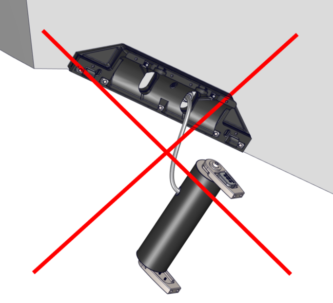
ATTENTION: Once the Seal Plate is removed, the Actuator will be unsupported. DO NOT allow the Actuator to hang by the cable. Use a table, strap, or some other method to support the weight of the Actuator.
- Remove the five (5) M8 Nuts, Wedge Lock Washers, and Cylindrical Washers holding the Actuator Plate and Wedge Plates.
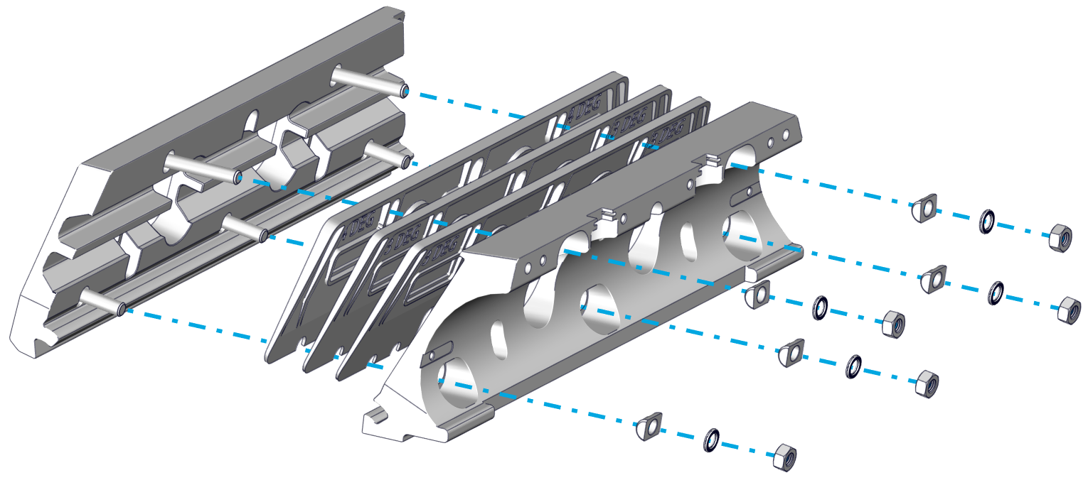
- Remove the Actuator Plate and switch Wedge Plates as needed.
- Adhesive may have seeped into cavities of the components during initial installation, which will cause them to hold in place even after the M8 Nuts are removed. A rubber mallet or another non-marring tool may be used to gently break away the components from the small amount of adhesive.
- For Concealed Cable Routing: Older versions of the Wedge Plates do not have openings in the bottom of the oval holes to allow the Wedge Plates to be removed past the Actuator Cable. This will require the Actuator Cable to be completey removed. Follow the initial steps in the Actuator Replacement guide to unpin and remove the Actuator Cable.
- Reassemble the Wedge Pack with the altered Wedge Plate combination and the Actuator Plate. Attach using the five (5) Cylindrical Washers, Wedge Lock Washers, and M8 Nuts, in that order. Torque to 130 in-lbs (14.7 N-m).
- Follow the steps in Section 12.1 or 12.2 of the Mechanical Installation Manual (750-1500) in order to re-install the Controller components.
- Apply additional threadlocker if the original threadlocker has worn off (Vibra-Tite VC-3 recommended).
- Remember to reinstall bonding wires and Anodes.
- Note torque values:
- Anode Screws – 25 in-lbs (2.8 N-m)
- Seal Plate bottom bolts – 80 in-lbs (9.0 N-m)
- Seal Plate top bolts – 50 in-lbs (5.6 N-m)
- Blade Bolts – 130 in-lbs (14.7 N-m)