Mechanical Installation Manual (750-1500)
5.4 Engine Spacing
NOTE: For all installations it is vital to ensure the Ride equipment is mounted such that the propulsion equipment is able to articulate through its full range of travel including trim, tilt and steering without any contact between Ride and propulsion.
Inboard and Podded Propulsion Applications
For Inboard and Podded Propulsion boats where Ride is mounted aft of the propeller, the Ride mounting location should not take into consideration the propellers and should only mount as far outboard as possible. Podded Propulsion includes but not limited to Mercury ®/Cummins ®Zeus Drive ®and Volvo ® IPS Drive ®.
Ride recommends utilizing two (2) Controllers if the hull size and shape allows. In the event the hull has propeller tunnels or other novel hull features which prevent two (2) Controller installation should consider four (4) Controllers to allow best Ride authority over the hull. Testing has shown comparable performance in two (2) and four (4) Controller installations.
For larger hulls where span requirements exceed 750 mm, the 900 through 1500 series all utilize four (4) controllers.
Outboard and Sterndrive (Inboard/Outboard) Applications
For Outboard and Sterndrive (I/O) applications where Seakeeper Ride is mounted forward of the propeller, the following guidance should be used to determine best locations for controllers relative to the propellers. Location must consider hull shape and propeller location in these boats.

NOTE: Seakeeper has performed successful testing with Seakeeper Ride overlapping propellers significantly further than indicated below; however, because of the infinite variables (engine height, engine trim, engine longitudinal offset from Seakeeper Ride Controllers, propeller selection, propeller rotation, sea conditions, loading conditions, vessel characteristics, and more) which impact the interaction between Seakeeper Ride and propulsors, Seakeeper cannot provide more specialized guidance or blanket recommendation to install with more propeller overlap than indicated below. If the Builder, Owners, or Operators choose to install the Seakeeper Ride Controllers with more propeller overlap than indicated in the figure below, it may result in rpm/coolant fluctuation and/or engine faults. Please see the Operation Manual for additional detail on Seakeeper Ride’s potential impacts to propulsors.
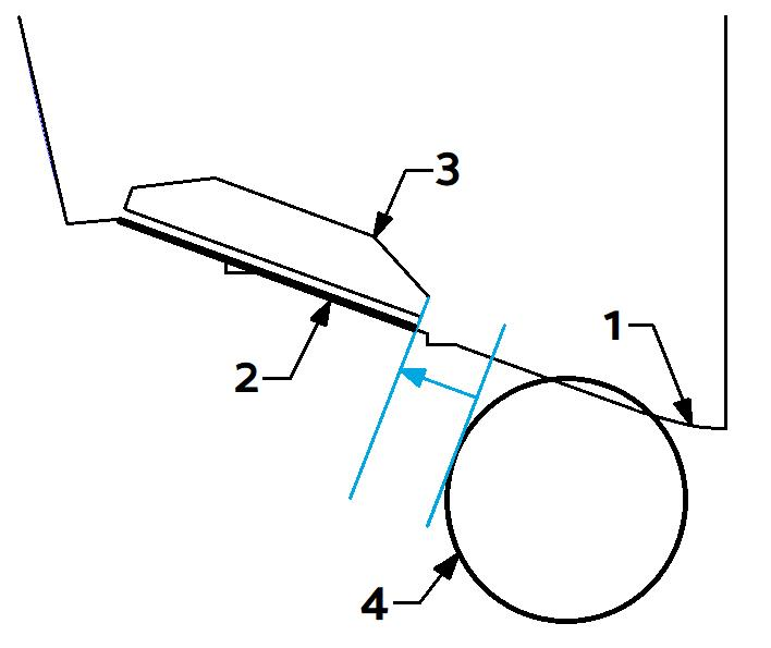
Due to the Controllers potential to change water flow into the boat’s propellers, it is recommended the Controllers be spaced around the propellers when possible.
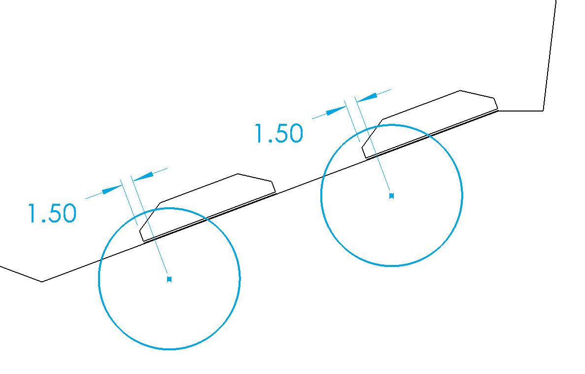
Where possible, it is recommended that the inner edge of the outboard controller, be mounted outboard of the diameter of the propeller tip (see the figure below). The line defining this instruction is the tangent line to the diameter of the propeller tip on the outboard side, perpendicular to the deadrise. Label 4 indicates the diameter of the propeller tip.
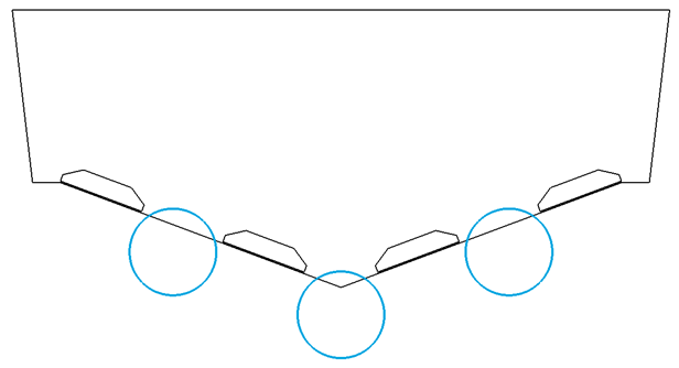
5.6.1 Three (3) Outboard or Sterndrive Engine Applications
For installations with Triple Outboards or Sterndrive (Inboard/Outboards (I/O)) we recommend the following guidance for locating the controllers:
Two (2) Seakeeper Ride Controllers on three (3) Outboard or Sterndrive Engine Applications
If two (2) Controllers are selected, the controllers should be mounted as far outboard to the hull side as indicated in Section 5.3.
Four (4) Seakeeper Ride Controllers on three (3) Outboard or Sterndrive Engine Applications
If four (4) Controllers are selected, the outside controller to be as far up the chine as possible.
The inside controller is to be centered between the engines. If there is Controller overlap of propellers, the inside controller should be such that the Blades of all four (4) controllers overlaps of all three (3) propellers evenly.
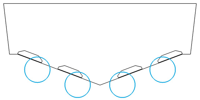
5.6.2 Four (4) Outboard or Sterndrive Engine Applications
For installations with Quad Outboards or Sterndrive (Inboard/Outboards (I/O)) we recommend the following guidance for locating the controllers:
Two (2) Seakeeper Ride Controllers on four (4) Outboard and Sterndrive Engine Applications
If two (2) Controllers are selected, the controllers should be mounted as far outboard to the hull side as indicated in Section 5.3.
Four (4) Seakeeper Ride Controllers on four (4) Outboard and Sterndrive Engine Applications
If four (4) Controllers are selected, the outside controller to be as far up the chine as possible.
The inside controller should be such that the Blades of all four (4) controllers overlap all four (4) propellers evenly. Measuring for this can be simplified by setting the distance from the outboard engine centerline to the outboard controller centerline the same as the distance from the inboard engine centerline to the inboard controller centerline.
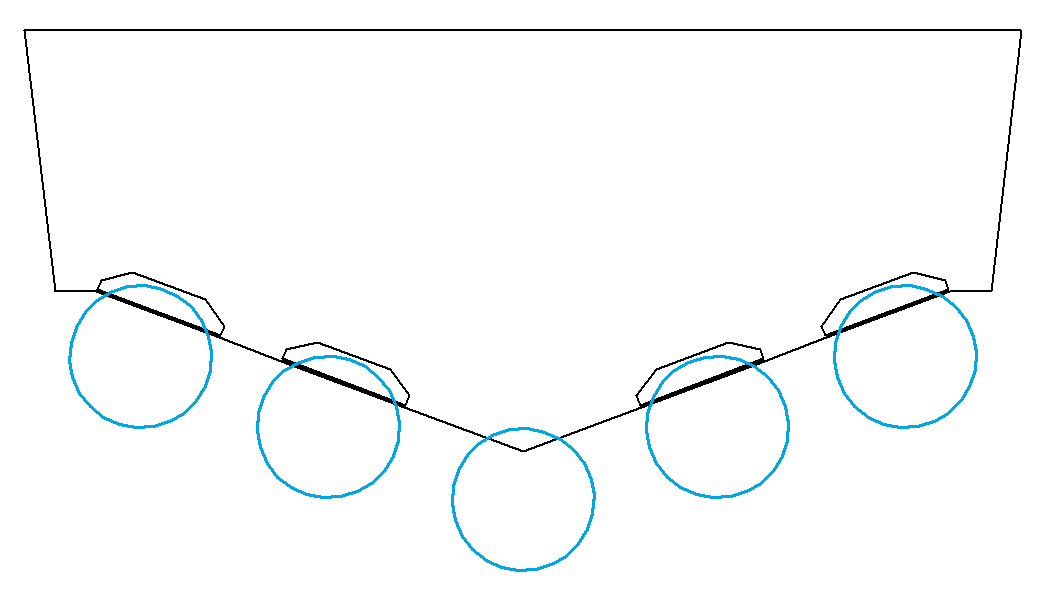
5.6.3 Five (5) Outboardor Sterndrive Engine Applications
For installations with Quint Outboards or Sterndrive (Inboard/Outboards (I/O)) we recommend the following guidance for locating the controllers:
Two (2) Seakeeper Ride Controllers on five (5) Outboard or Sterndrive Engine Applications
If two (2) Controllers are selected, the controllers should be mounted as far outboard to the hull side as indicated in Section 5.3.
Four (4) Seakeeper Ride Controllers on five (5) Outboard or Sterndrive Engine Applications
If Four (4) Controllers are selected, the outside controller is to be as close to the chine as possible.
The inside controller should be such that all four (4) controllers overlap the outer four (4) engines evenly.