Mechanical Installation Manual (750-1500)
12. Actuator and Blade Installation
Actuator and Blade Installation Introduction
The final stages of installation are differentiated by the cable entry into the hull. If you are following a concealed cable entry, follow the procedure detailed in Section 12.1. For exposed cable entry, follow procedure in Section 12.2.
Note: Do not bend the Actuator Cable at a radius smaller than 50 mm (1.97 in.) to avoid damaging the cable. Do not lift the Actuator by the cable when removing from the box or anytime carrying.
12.1 Concealed Cable Entry

ATTENTION: DO NOT pickup the Actuator by the cable or allow it to hang by the cable. Doing so could compromise to the watertight seal of the Actuator and cause system malfunction.
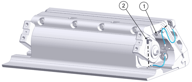
- Place the Actuator into the Actuator Plate, aligning the cable gland in the slot provided in the Actuator Plate. The Actuator can be mounted either way, so the cable is in the left or right slot. The arms should be pointed out toward the installer. One arm is stiffer than the other.
- Position the Seal Plate over the arms and Actuator and align the countersunk holes on the bottom surface.
- On Dual Controller systems the two (2) supplied plastic debris caps will need to be inserted between the Seal Plate and Actuator Plate at this stage. See Figure 67 below.
- Thread in the top four (4) M6-1.0 x 30 mm Hex Head Bolts with M6 Washers to align the Seal Plate with the Wedge Pack Assembly, but do not tighten. There should be a small gap (about 2 mm) between the top of the Seal Plate and the Actuator Plate. (Quantity four [4] bolts for 525 Controllers and six [6] for 750 mm Controllers)
- Visually center the Actuator to the Seal Plate by comparing small length of protruding Actuator housing on each end.
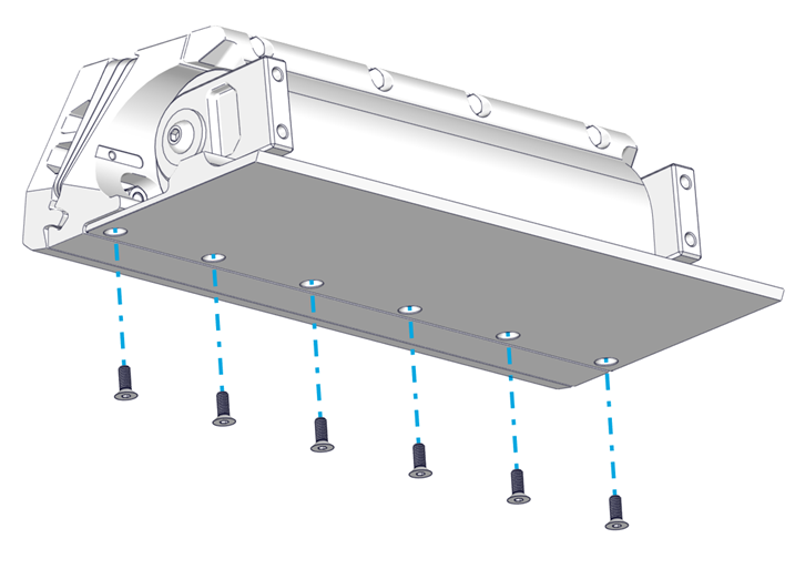
- Insert the bottom six (6) M6-1.0 x 16 mm Torx Flathead Screws. Torque to 80 in-lbs (9 N-m) in an alternating pattern. Repeat the top torquing sequence two (2) times or until the bolts do not rotate when achieving the torque. (Quantity nine [9] bolts for 525 Controllers and ten [10] for 750 mm Controllers)

- Torque the top four (4) M6-1.0 x 30 mm Hex Head Bolts to 50 in-lbs (5.7 N-m) in an alternating pattern. Repeat the top torquing sequence two (2) times or until the bolts do not rotate when achieving the torque. This ensures an even clamping force is applied across the Actuator. (Quantity four [4] bolts for 525 Controllers and six [6] for 750 mm Controllers)
- Ensure rubber gromet is present in Cable Gland and then Tighten the Cable Gland on the inboard side of the transom. The Cable Gland should be snug to prevent leaking, but do not overtighten. Gently pull on the cable to ensure there is no movement and prove it is sealing securely.
Verify Seal Plate Angle
At this point the Seal Plate angle can be verified with a straight edge to ensure the wedge pack selection was correct. Following the procedure from Section 6.2 to check the angle of the Seal Plate. If adjustments are desired, remove Seal Plate and rebuild the Wedge Pack following Section 7 in place until desired Seal Plate angle is achieved.
Note: The Cable Gland must have the rubber grommet in place to properly seal. The outside of the cable must be clean of debris, dust, adhesives, etc. to properly seal. Do not allow acetone to come in contact with the Controller Cable Gland Sealing Nut.
- Attach the bonding wires and Actuator Plate Anodes.
- Attach one terminal end of one shorter bonding wire to the upper right corner of the Transom Plate using one (1) M5-0.8 x 10 mm Hex Head Screw.
- Attach one terminal end of another shorter bonding wire the front right-hand side of the Seal Plate using one (1) M5-0.8 x 10 mm Hex Head Screw.
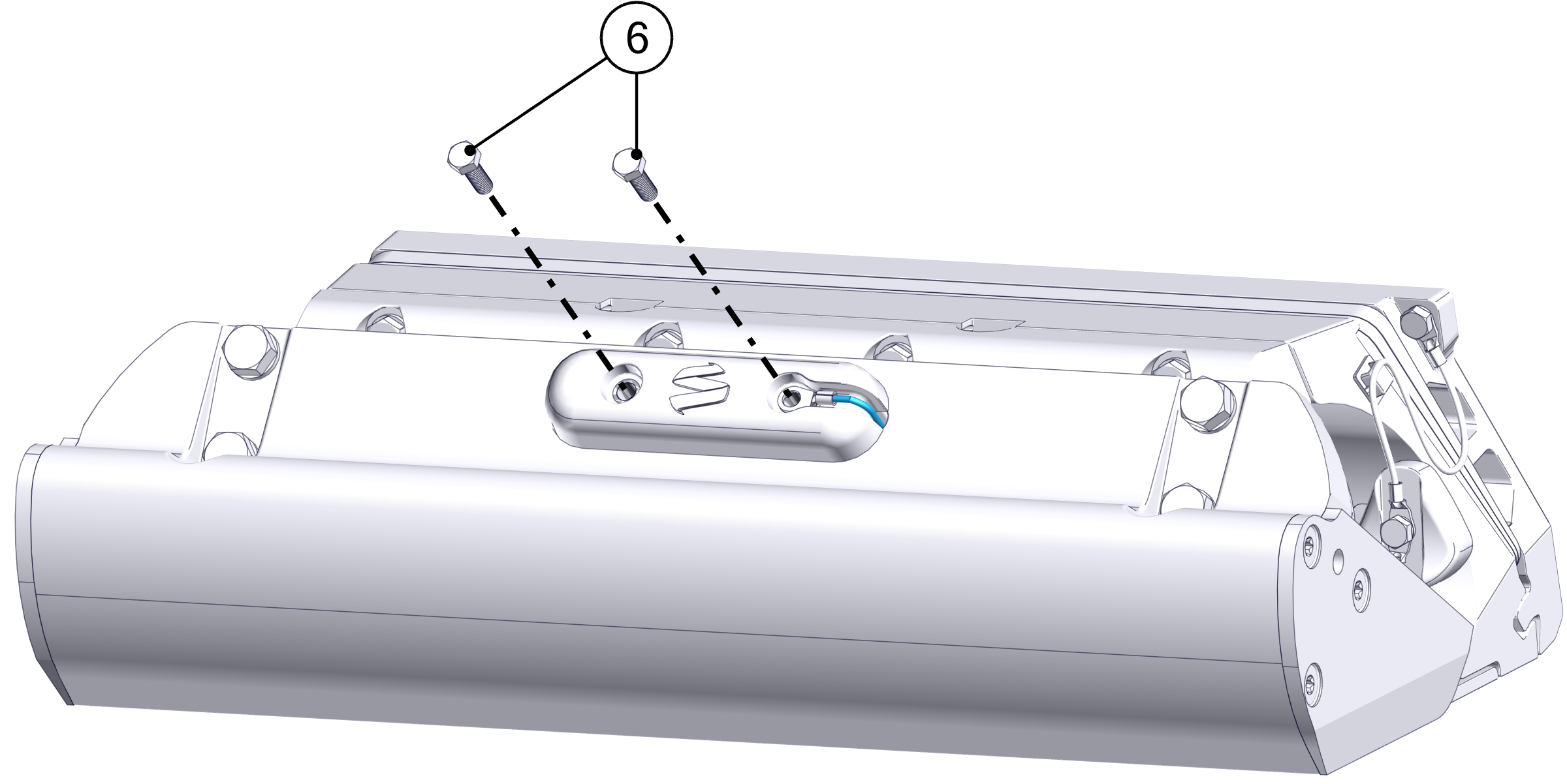
- Install the two (2) Actuator Plate Anodes using two M5-0.8 x 20 mm Hex Head Screws. Slide the two free terminal ends of the bonding wires over the right-hand anode screw while inserting creating a continuous connection between the Transom Plate, Actuator Plate, and Seal Plate.
- Note: Install the wire to the starboard side arm before mounting the Blade.
- Attach one terminal end of the longer bonding wire to the right side Blade Arm using one (1) M5-0.8 x 10 mm Hex Head Screw.
- Install the Blade to the Actuator Arms using the four (4) M8-1.25 x 30 mm Hex Head Bolts and their washers. Slide the free bonding wire terminal end through the elongated hole near the center of the Blade. Before torquing the bolts, push the Actuator Arms firmly down against the Blade supporting edge. Torque these four (4) bolts to 130 in-lbs (14.7 N-m) in an ‘X’ pattern.
- Once installed, push the Blade all the way down and verify that the Blade is not contacting the Seal Plate. There should be a small, even gap between the Blade and the Seal Plate.
- Before torquing, the Blade can be slid up and down slightly to bring it closer and farther away from the Seal Plate, respectively. If the Blade is rubbing and creating friction against the Seal Plate, or if the gap appears too large, adjust the Blade accordingly. Contact Seakeeper if there are still concerns with Blade gap tolerance after following these instructions.
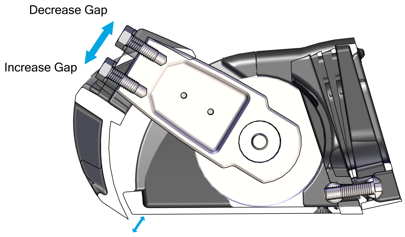
Note: Maintaining this gap between the Blade and Seal Plate is critical to maintaining factory tested failure mode performance. If the gap between the Blade and Seal Plate is too large, system performance will fall off. If the Blade contacts the Seal Plate, the friction will slow down the system’s response time, also reducing performance.
To maintain the factory fitment:
- Do not apply anti-fouling coating to the surfaces between the Blade and Seal Plate in order to avoid changing the fit of those parts.
- Always keep the surfaces between the Blade and Seal Plate clean and free from debris, including naturally occurring debris (such as marine debris) and other debris (such as paint or coating.
- When repairing or replacing any components on the Controller, confirm that the Blade rotates by hand. Resistance will be felt from the Actuator, but there must be no additional grinding or friction inhibiting movement.
- Install the Blade Anode using two (2) M5-0.8 x 16 mm Hex Head Screws. Slide the other terminal end of the bonding wire over the right-hand side screw while inserting.
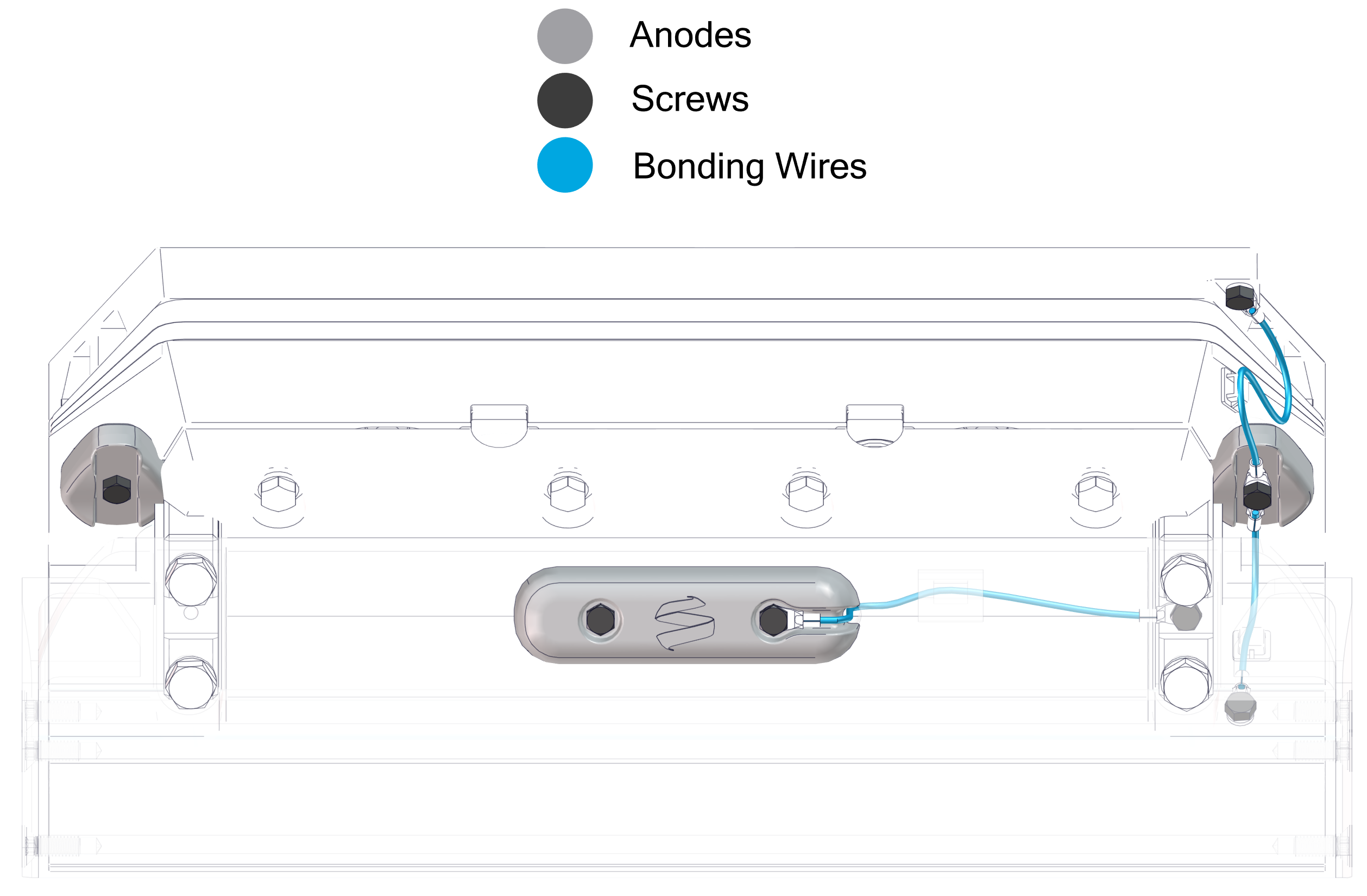
When complete, the anodes and bonding wires should be connected as shown below.
12.2 Exposed Cable Entry
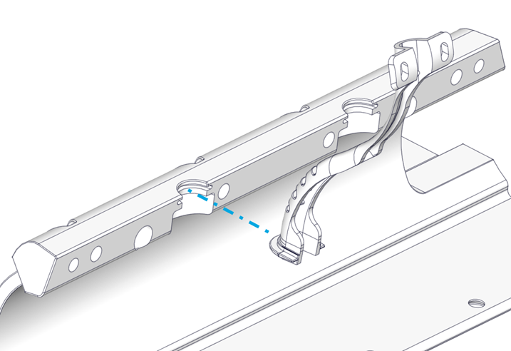
- Install the Cable Guide Support in the groove in the Seal Plate.
- Place the Actuator into the Actuator Plate. The Actuator can be mounted with cable exiting to port or starboard side, so select the correct side to align with the Cable Guide. The arms should be pointed out toward the installer. One arm is stiffer than the other.
- Position the Seal Plate over the arms and Actuator and align the countersunk holes on the bottom surface.
- On Dual Controller systems the two (2) supplied plastic debris caps will need to be inserted between the Seal Plate and Actuator Plate at this stage. See Figure 67.
- Route the Actuator Cable through the Cable Guide Support.
- Thread locker and thread in the top four (4) M6-1.0 x 30 mm Hex Head Bolts with M6 Washers to align the Seal Plate with the Wedge Pack Assembly, but do not tighten. There should be a small gap (about 2 mm) between the top of the Seal Plate and the Actuator Plate. (Quantity four [4] bolts for 525 Controllers and six [6] for 750 mm Controllers) See Figure 66 – Seal Plate Top Screw Installation.
- Visually center the Actuator to the Seal Plate by comparing small length of protruding Actuator housing on each end.
- Apply thread locker and insert the bottom six (6) M6-1.0 x 16 mm Torx Flathead Screws. Torque to 80 in-lbs (9 N-m) in an alternating pattern. Repeat the top torquing sequence two (2) times or until the bolts do not rotate when achieving the torque (Quantity nine [9] bolts for 525 Controllers and ten [10] for 750 mm Controllers) See Figure 69 – Bottom Bolts Installation.
- Torque the top four (4) M6-1.0 x 30 mm Hex Head Bolts to 50 in-lbs (5.7 N-m) in an alternating pattern. Repeat the top torquing sequence two (2) times or until the bolts do not rotate when achieving the torque. This ensures an even clamping force is applied across the Actuator. (Quantity four [4] bolts for 525 Controllers and six [6] for 750 mm Controllers).
Verify Seal Plate Angle
At this point the Seal Plate angle can be verified with a straight edge to ensure the wedge pack selection was correct. Following the procedure from Section 6.2 to check the angle of the Seal Plate. If adjustments are desired, remove Seal Plate and rebuild the Wedge Pack following Section 7 in place until desired Seal Plate angle is achieved.
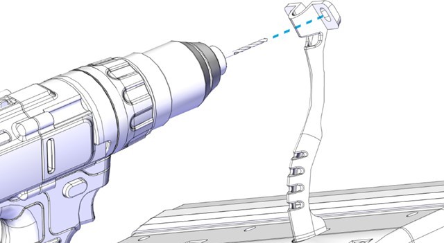
- Mount the Cable Guide Support in line with the natural path of the Actuator Cable to the transom. Pre-drill two (2) mounting screw pilot holes using a 3/32 in. (2.4 mm) bit. Inject sealant into the holes. Insert two (2) No. 8 x 0.75 in. screws and tighten with a Phillips head screwdriver.
- Route the Actuator cable over the Inner Cable Guide. Feed as much cable as possible through the Cable Gland Tube.
- Tighten the Cable Gland around the Actuator Cable on the inboard side of the transom (See Figure 70 – Cable Gland Installation Inboard of Transom). The Cable Gland should be snug to prevent leaking, but do not overtighten. If the Cable Gland was not selected, apply marine adhesive sealant to the cable sheath and cable hole to seal the penetration from outside the hull. Note: The Cable Gland must have the rubber grommet in place to properly seal. The outside of the cable must be clean of debris, dust, adhesives, etc. to properly seal. Do not allow acetone to come in contact with the Controller Cable Gland Sealing Nut.
- Place the Outer Cable Guide over the Inner Cable Guide. Mark the location of the six (6) mounting screw holes. Drill 3/32 (2.4 mm) pilot holes in these six (6) locations.
- Inject sealant into the pilot holes for the mounting screws for the Outer Cable Guide. Using a Phillips head screwdriver, install the six (6) mounting screws into the hull and hand-tighten.
- Attach the bonding wires and Actuator Plate Anodes.
- Attach one terminal end of one bonding wire to the upper right corner of the Transom Plate using one (1) M2-0.7 x 6 mm Phillips Head Screw.
- Attach one terminal end of another bonding wire the front right-hand side of the Seal Plate using one (1) M2-0.7 x 6 mm Phillips Head Screw.
- Install the two (2) Actuator Plate Anodes using two M5-0.8 x 20 mm Button Head Screws. Slide the two free terminal ends of the bonding wires over the right-hand anode screw while inserting creating a continuous connection between the Transom Plate, Actuator Plate, and Seal Plate.
- Note: Install the wire to the starboard side arm before mounting the Blade.
- Install the Blade to the Actuator Arms using the four (4) M8-1.25×20 mm screws and their washers. Before torquing the bolts, push the Actuator Arms firmly down against the Blade supporting edge. Torque these four (4) bolts to 80 in-lbs (9.0 N-m) in an ‘X’ pattern (Figure 72 – Blade Installation).
- Once installed, push the Blade all the way down and verify that the Blade is not contacting the Seal Plate. There should be a small, even gap between the Blade and the Seal Plate. Contact Seakeeper if the Blade does not meet this requirement.
- Before torquing, the Blade can be slid up and down slightly to bring it closer and farther away from the Seal Plate, respectively. If the Blade is rubbing and creating friction against the Seal Plate, or if the gap appears too large, adjust the Blade accordingly. Contact Seakeeper if there are still concerns with Blade gap tolerance after following these instructions. (Figure 73 – Blade Gap Adjustment)
Note: Maintaining this gap between the Blade and Seal Plate is critical to maintaining factory tested failure mode performance. If the gap between the Blade and Seal Plate is too large, system performance will fall off. If the Blade contacts the Seal Plate, the friction will slow down the system’s response time, also reducing performance.
To maintain the factory fitment:
- Do not apply anti-fouling coating to the surfaces between the Blade and Seal Plate in order to avoid changing the fit of those parts.
- Always keep the surfaces between the Blade and Seal Plate clean and free from debris, including naturally occurring debris (such as marine debris) and other debris (such as paint or coating.
- When repairing or replacing any components on the Controller, confirm that the Blade rotates by hand. Resistance will be felt from the Actuator, but there must be no additional grinding or friction inhibiting movement.
- Install the Blade Anode using two M5-0.8 x 20 mm Button Head Screws. Slide the other terminal end of the bonding wire over the right-hand side screw while inserting. (Figure 74 – Blade Anode Installation)
See Figure 75 for Anode and Bonding Wire overview.
6.3 Wedge Pack Angle Adjustment
For Seakeeper Ride 750-1500, the Wedge Pack angle can be adjusted after installation. Proper care must be taken during the initial installation procedure to make adjustment as smooth as possible.
Notes for Initial Installation
- Adhesive may seep into the cavities of the Wedge Pack during installation, which will make removal of the Actuator Plate and Wedge Plates difficult. Before adhering, place masking tape on the inside of the oval holes. While mounting, clean adhesive from the oval holes and as much of the other holes and gaps as possible.
- The Wedge Pack angle options are split into two halves based on bolt length. See Table 3. Once the Transom Plate is adhered to the boat, the bolts cannot be changed, meaning only Wedge Pack angle options corresponding the the bolt lengths present will be available.
Wedge Pack Angle Adjustment
Reverse the steps in Section 12.1 or 12.2 of the Mechanical Installation Manual (750-1500) to remove all components aft of the Wedge Pack. The Wedge Pack bolts can then be loosened to adjust the Wedge Plates selection. See detailed steps below:
Note: Bolt count and images are for 750 Quad Controllers, and will vary slightly depending on Controller size.
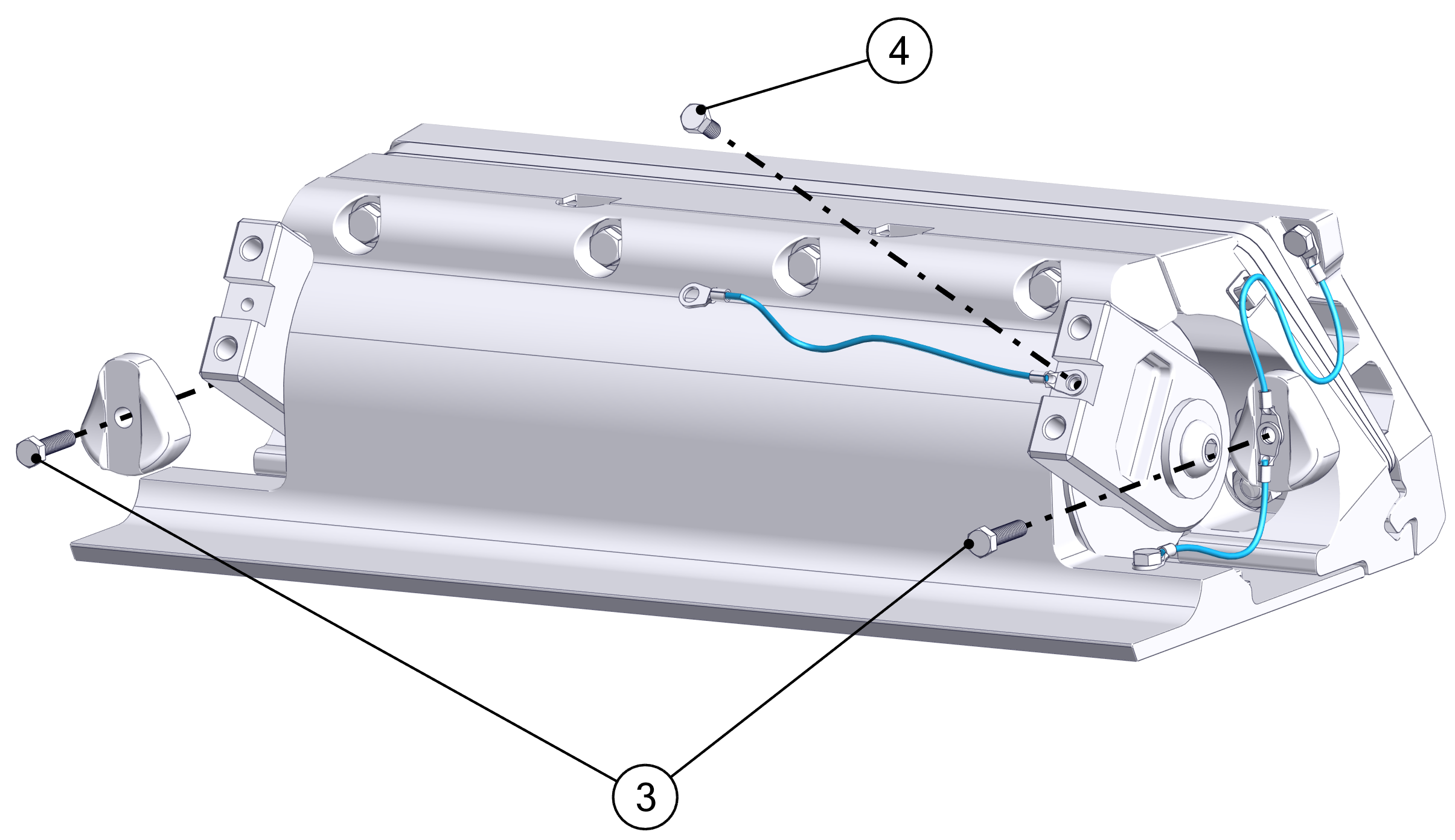
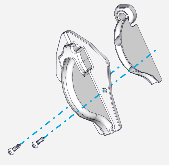
- Remove the two (2) M5-0.8 x16 Hex Head Screws holding the Blade Anode in place.
- Remove the four (4) M8-1.25 x 20 mm Hex bolts holding the Blade in place, and set the Blade aside.
- Remove the five (5) M5 Hex Head Screws holding the bonding wires and Actuator Plate Anodes.
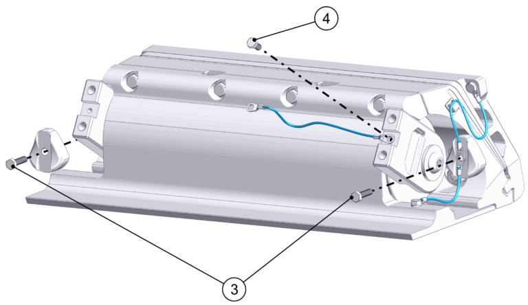
- If Concealed Actuator Cable routing is present, loosen the Cable Gland from the inside of the boat to allow the Actuator cable to move freely once the Seal Plate is removed. If Exposed Acutator Cable routing is present, remove the two (2) Phillips Screws holding the Cable Guide Support in place.
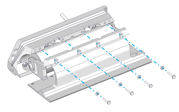
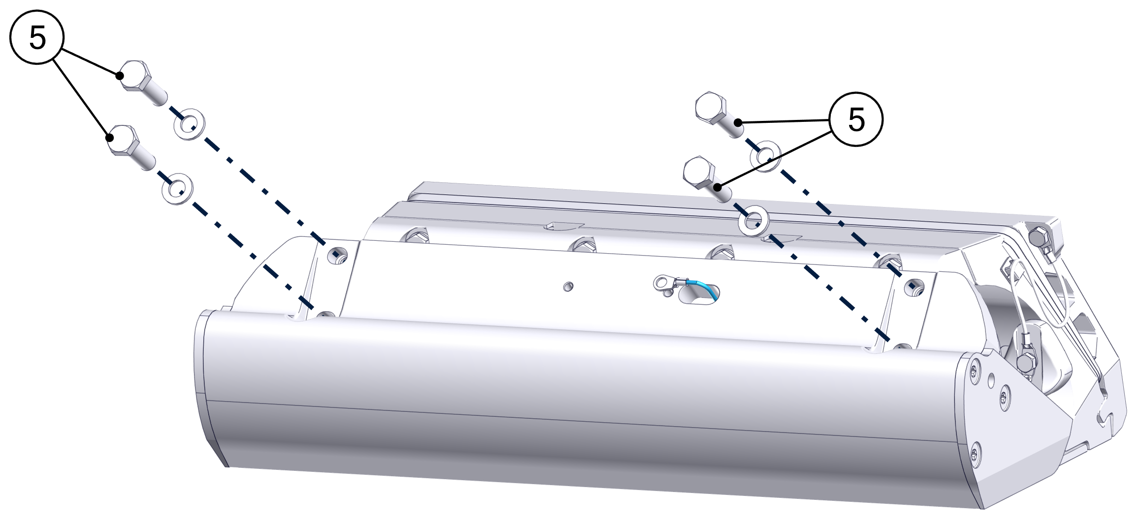
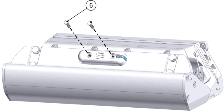
- Loosen the top four (4) M6-1.0 x 30 mm Hex Head Bolts. Remove the bottom six (6) M6-1.0 x 16 mm Torx Flathead Screws. Remove the top four (4) M6-1.0 x 30 mm Hex Head Bolts, which will allow the Seal Plate and Actuator to be removed. Gently pull the Actuator Cable out far enough for Wedge Pack adjustment. Support the Actuator.

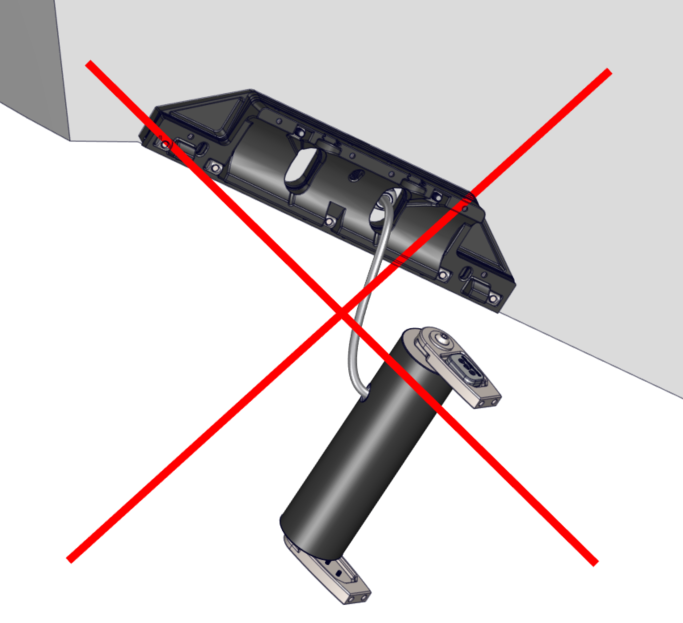
ATTENTION: Once the Seal Plate is removed, the Actuator will be unsupported. DO NOT allow the Actuator to hang by the cable. Use a table, strap, or some other method to support the weight of the Actuator.
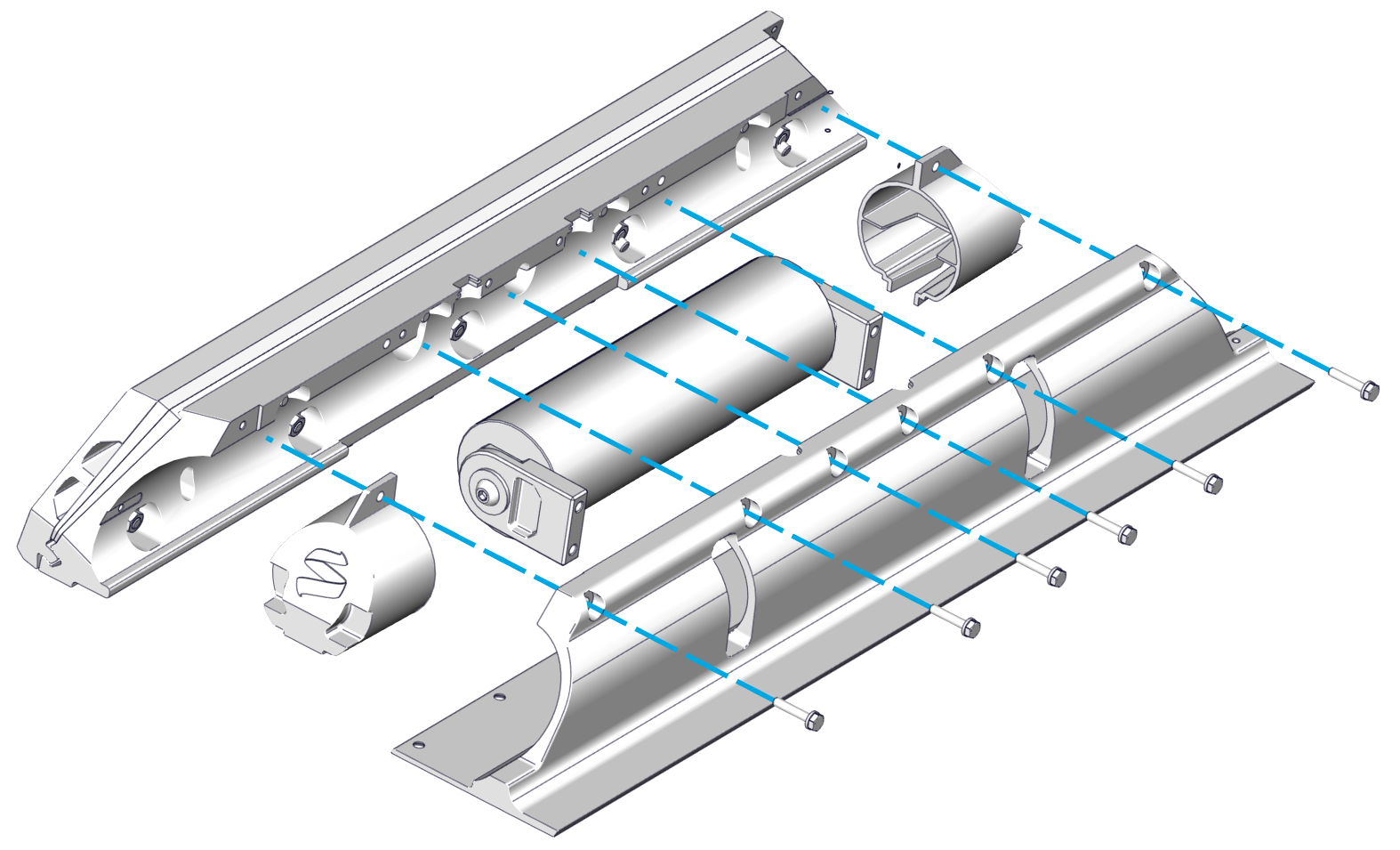
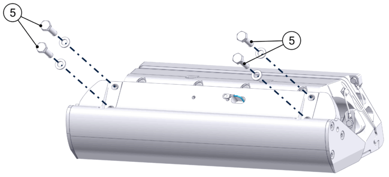
- Remove the five (5) M8 Nuts, Wedge Lock Washers, and Cylindrical Washers holding the Actuator Plate and Wedge Plates.
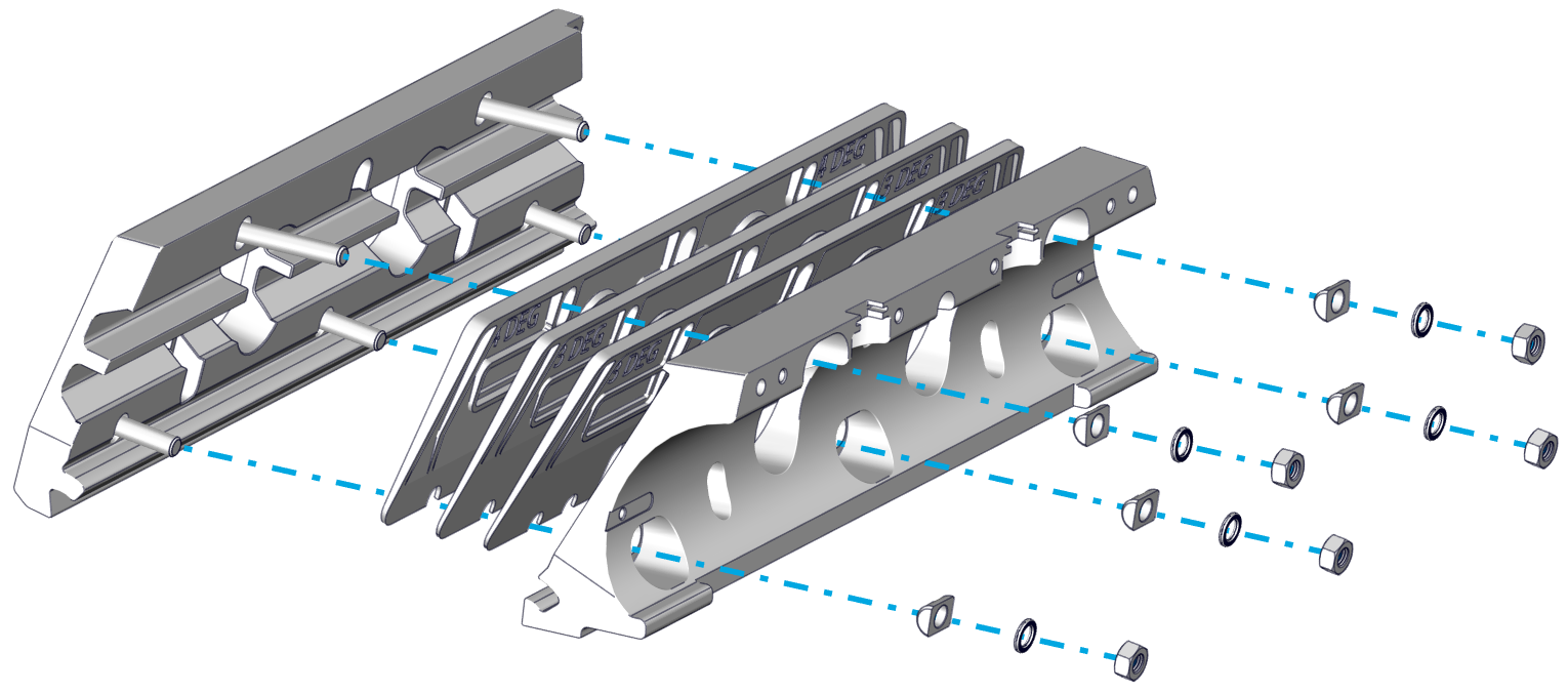
- Remove the Actuator Plate and switch Wedge Plates as needed.
- Adhesive may have seeped into cavities of the components during initial installation, which will cause them to hold in place even after the M8 Nuts are removed. A rubber mallet or another non-marring tool may be used to gently break away the components from the small amount of adhesive.
- For Concealed Cable Routing: Older versions of the Wedge Plates do not have openings in the bottom of the oval holes to allow the Wedge Plates to be removed past the Actuator Cable. This will require the Actuator Cable to be completey removed. Follow the initial steps in the Actuator Replacement guide to unpin and remove the Actuator Cable.
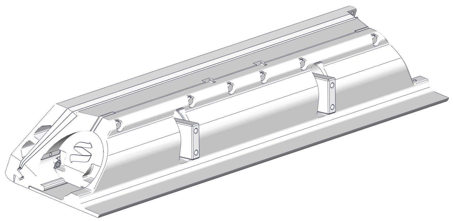
- Reassemble the Wedge Pack with the altered Wedge Plate combination and the Actuator Plate. Attach using the five (5) Cylindrical Washers, Wedge Lock Washers, and M8 Nuts, in that order. Torque to 130 in-lbs (14.7 N-m).
- Follow the steps in Section 12.1 or 12.2 of the Mechanical Installation Manual (750-1500) in order to re-install the Controller components.
- Apply additional threadlocker if the original threadlocker has worn off (Vibra-Tite VC-3 recommended).
- Remember to reinstall bonding wires and Anodes.
- Note torque values:
- Anode Screws – 25 in-lbs (2.8 N-m)
- Seal Plate bottom bolts – 80 in-lbs (9.0 N-m)
- Seal Plate top bolts – 50 in-lbs (5.6 N-m)
- Blade Bolts – 130 in-lbs (14.7 N-m)